Home › Engine / Hybrid System › 2AD-FTV ENGINE CONTROL › ECD SYSTEM
NM3090E _51 Engine / Hybrid System _008660 2AD-FTV ENGINE CONTROL _0048045 ECD SYSTEM DE DETAILS F

2AD-FTV ENGINE CONTROL  ECD SYSTEM  DETAILS  ACCELERATOR PEDAL SENSOR  


CONSTRUCTION


a.

Automatic Transaxle Models

i.

The non-contact type accelerator pedal sensor assembly uses a Hall IC.


ii.

The magnetic yoke mounted at the base of the accelerator pedal arm moves around the Hall IC in accordance with the amount of effort applied to the accelerator pedal. The Hall IC converts the changes in the magnetic flux that occur into electrical signals, and outputs them in the form of accelerator pedal effort to the ECM.


iii.

This accelerator pedal sensor assembly includes 2 Hall ICs and circuits for the main and sub signals. The accelerator pedal sensor assembly converts the accelerator pedal depressed angles into electric signals with 2 differing characteristics and outputs them to the ECM.


iv.

When the depressing force applied to the accelerator pedal is greater than a predetermined amount, the ECM detects a "kick down on" from the VPA signal provided by the accelerator pedal position sensor.
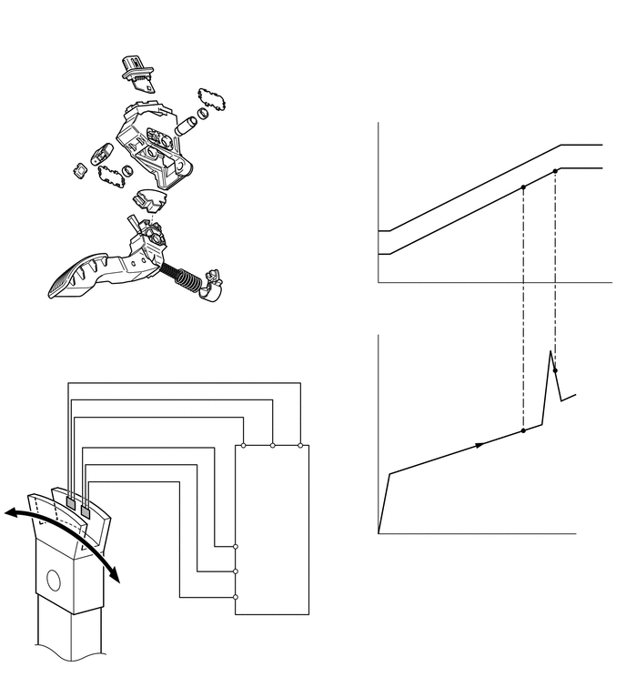
W100199
0.5,5.302 0.615,5.302 0.615,5.302 0.792,5.75 true 1.417,5.646 1.229,5.646 1.229,5.646 1,5.865 true 1.375,6.281 1.271,6.281 1.271,6.281 1.208,6.104 true 1.375,7.281 1.042,7.281 true 4.823,0.802 5.042,0.802 5.042,0.802 5.99,2.135 true 6.354,1.938 6.552,0.49 6.552,0.49 6.323,0.49 false 2.167,0.688 2,0.688 2,0.688 1.719,0.99 true 0.854,1.135 1.031,1.135 1.031,1.135 1.458,1.448 true 0.917,2.375 1.135,2.375 1.135,2.375 1.531,2.948 true 2.365,2.51 2.146,2.51 2.146,2.51 1.833,2.26 true 3.573,4.469 4.323,5 0.75,0.531 10 Depressing Force 2.406,4.896 2.813,5.146 0.406,0.25 9 VCPA 2.854,4.896 3.156,5.156 0.302,0.26 9 EPA 3.188,4.896 3.604,5.177 0.417,0.281 9 VPA 2.958,6.063 3.292,6.375 0.333,0.313 10 ECM 0.073,5.208 0.542,5.479 0.469,0.271 10 Hall IC 1.479,5.542 1.979,5.813 0.5,0.271 10 Hall IC 2.323,6.26 2.698,6.521 0.375,0.26 10 VPA2 2.313,6.552 2.688,6.813 0.375,0.26 10 EPA2 2.292,6.844 2.688,7.104 0.396,0.26 10 VCP2 1.438,6.188 2.073,6.74 0.635,0.552 10 Magnetic Yoke 1.438,7.198 2.167,7.75 0.729,0.552 10 Accelerator Pedal Arm 4.219,6.042 4.354,6.271 0.135,0.229 10 0 4.073,3.781 4.344,4.073 0.271,0.292 10 (N) 4.073,1.313 4.344,1.604 0.271,0.292 10 (V) 4.396,6.146 6.708,6.438 2.313,0.292 10 Accelerator Pedal Depressed Angle 4.219,3.208 4.354,3.49 0.135,0.281 10 0 4.594,2.188 4.979,2.438 0.385,0.25 10 VPA2 5,2.708 5.313,2.979 0.313,0.271 10 VPA 3.854,0.708 4.792,1.292 0.938,0.583 10 Output Voltage at Full Open 5.24,0.406 6.302,0.938 1.063,0.531 10 Kick Down Mode Voltage 3.74,2.063 4.26,2.625 0.521,0.563 10 Output Voltage 2.208,0.594 2.708,0.865 0.5,0.271 10 Hall IC 0.344,1.042 0.948,1.583 0.604,0.542 10 Sensor Housing 0.167,2.26 0.948,2.844 0.781,0.583 10 Accelerator Pedal Arm 2.427,2.427 3.083,3.01 0.656,0.583 10 Magnetic Yoke


b.

Manual Transaxle Models

i.

The non-contact type accelerator pedal position sensor uses a Hall IC.


ii.

The magnetic yoke mounted at the accelerator pedal arm rotates around the Hall IC in accordance with the amount of effort applied to the accelerator pedal. The Hall IC converts the changes in the magnetic flux into electrical signals, and outputs them as accelerator pedal effort to the ECM.


iii.

The Hall IC contains circuits for the main and sub signals. The accelerator pedal position sensor converts the accelerator pedal depressed angles into electric signals with 2 differing characteristics and outputs them to the ECM.
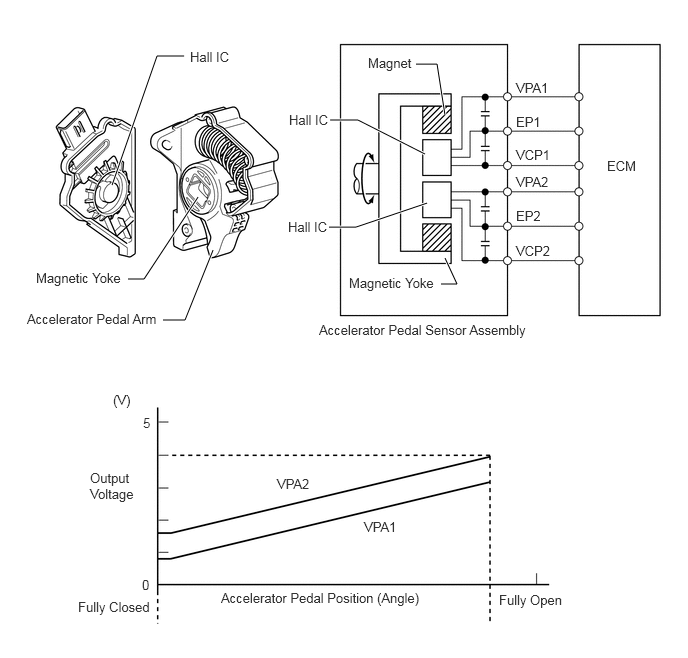
W100142E21
1.167,1.927 1.635,0.583 1.635,0.583 1.917,0.583 true 2.219,2.604 1.927,3.333 1.927,3.333 1.698,3.333 true 4.635,1.198 4.552,0.667 4.552,0.667 4.333,0.667 true 4.427,1.604 3.729,1.25 3.729,1.25 3.438,1.25 true 4.448,2.115 3.708,2.365 3.708,2.365 3.427,2.365 true 2.063,2.052 1.5,2.906 1.5,2.906 1.333,2.906 true 4.635,2.688 4.76,2.958 4.76,2.958 4.594,2.958 true 3.323,3.354 5.729,3.667 2.406,0.313 10 Accelerator Pedal Sensor Assembly 3.01,1.167 3.49,1.521 0.479,0.354 10 Hall IC 3.833,0.573 4.375,0.969 0.542,0.396 10 Magnet 3,2.281 3.479,2.635 0.479,0.354 10 Hall IC 1.177,4.083 1.469,4.49 0.292,0.406 10 (V) 1.49,4.323 1.615,4.656 0.125,0.333 10 5 0.938,4.896 1.427,5.615 0.49,0.719 10 Output Voltage 1.479,6.01 1.604,6.302 0.125,0.292 10 0 0.813,6.24 1.667,6.594 0.854,0.354 10 Fully Closed 5.198,6.167 5.948,6.5 0.75,0.333 10 Fully Open 2.302,6.146 4.479,6.448 2.177,0.302 10 Accelerator Pedal Position (Angle) 5.375,0.833 5.771,1.125 0.396,0.292 10 VPA1 5.375,1.188 5.771,1.479 0.396,0.292 10 EP1 5.375,1.531 5.771,1.823 0.396,0.292 10 VCP1 5.375,1.813 5.771,2.104 0.396,0.292 10 VPA2 5.375,2.167 5.771,2.458 0.396,0.292 10 EP2 5.375,2.531 5.771,2.823 0.396,0.292 10 VCP2 1.979,0.51 2.458,0.865 0.479,0.354 10 Hall IC 3.792,5.406 4.188,5.698 0.396,0.292 10 VPA1 2.885,4.958 3.281,5.25 0.396,0.292 10 VPA2 6.323,1.646 6.698,1.958 0.375,0.313 10 ECM 0.281,3.24 1.719,3.542 1.438,0.302 10 Accelerator Pedal Arm 0.375,2.813 1.406,3.177 1.031,0.365 10 Magnetic Yoke 3.635,2.865 4.667,3.229 1.031,0.365 10 Magnetic Yoke