NM3090E
_51
Engine / Hybrid System
_008670
2AD-FHV FUEL
_0048078
FUEL SYSTEM
DE
DETAILS
F
2AD-FHV FUEL FUEL SYSTEM DETAILS SUPPLY PUMP
CONSTRUCTION
a.
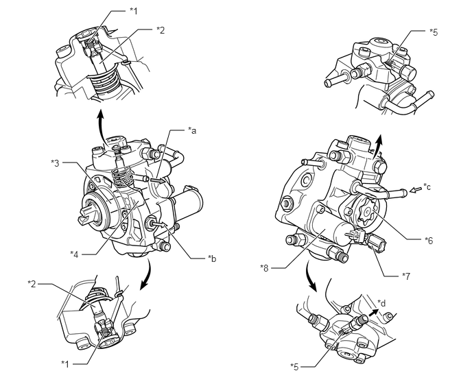
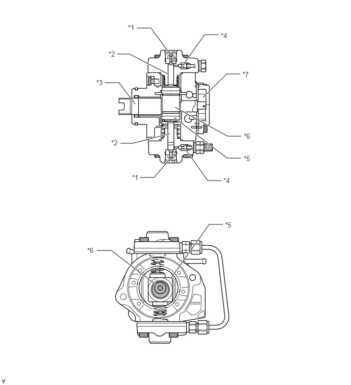
The supply pump assembly consists of an eccentric camshaft, a ring cam, 2 plungers, 4 check valves, a Suction Control Valve (SCV), a fuel temperature sensor and a feed pump.
b.
The 2 plungers are placed opposite each other outside of the ring cam.
2.375,2.708 2.583,1.979
2.583,1.979 2.802,1.979
true
1.51,0.969 2.094,0.448
2.094,0.448 2.313,0.448
true
0.573,4.313 0.792,4.313
0.792,4.313 1.448,4.667
true
1.104,5.531 1.323,5.531
1.323,5.531 1.583,5.063
true
1.24,3.865 1.458,3.865
1.458,3.865 2.104,3.052
true
0.948,2.469 1.167,2.469
1.167,2.469 1.688,3.094
true
5.906,0.938 6.24,0.469
6.24,0.469 6.458,0.469
true
4.115,4.073 4.333,4.073
4.333,4.073 4.938,3.479
true
4.563,5.573 4.781,5.573
4.781,5.573 5.208,5.052
true
1.354,0.635 1.688,0.167
1.688,0.167 1.906,0.167
true
2.49,3.417 2.896,3.927
2.896,3.927 3.115,3.927
true
5.656,3.188 6.177,3.635
6.177,3.635 6.396,3.635
true
5.646,3.729 5.833,4.198
5.833,4.198 6.052,4.198
true
1.969,0.083 2.281,0.24
0.313,0.156
10
*1
2.375,0.375 2.688,0.531
0.313,0.156
10
*2
0.771,2.396 1.083,2.552
0.313,0.156
10
*3
1.063,3.781 1.375,3.938
0.313,0.156
10
*4
6.521,0.406 6.833,0.563
0.313,0.156
10
*5
6.448,3.573 6.76,3.729
0.313,0.156
10
*6
6.104,4.115 6.417,4.271
0.313,0.156
10
*7
3.948,3.99 4.26,4.146
0.313,0.156
10
*8
2.854,1.896 3.167,2.052
0.313,0.156
10
*a
3.156,3.844 3.469,4
0.313,0.156
10
*b
6.427,2.75 6.74,2.906
0.313,0.156
10
*c
5.729,4.521 6.042,4.677
0.313,0.156
10
*d
0.927,5.448 1.24,5.604
0.313,0.156
10
*1
0.417,4.229 0.729,4.385
0.313,0.156
10
*2
4.406,5.49 4.719,5.646
0.313,0.156
10
*5
| *1 | Check Valve (for Suction) | *2 | Plunger |
| *3 | Eccentric Camshaft | *4 | Ring Cam |
| *5 | Check Valve (for Discharge) | *6 | Feed Pump |
| *7 | Fuel Temperature Sensor | *8 | SCV |
| *a | To Fuel Tank Assembly (for Return) | *b | To Exhaust Fuel Addition Injector |
| *c | From Fuel Tank Assembly (for Suction) | *d | To Common-rail Assembly |
3.49,3.219 3.146,3.625
3.146,3.625 2.854,3.625
true
3.448,1.521 2.646,1.104
2.646,1.104 2.396,1.104
true
2.76,2.125 2.427,1.688
2.427,1.688 2.135,1.688
true
3.469,2.729 2.708,2.927
2.708,2.927 2.458,2.927
true
3.219,5.844 2.271,5.115
2.271,5.115 1.979,5.115
true
3.479,1.115 3.083,0.573
3.083,0.573 2.792,0.573
true
4.458,0.708 4.177,0.708
4.177,0.708 3.74,1.323
true
4.906,1.51 4.625,1.51
4.625,1.51 4.146,1.99
true
4.521,3.688 4.24,3.688
4.24,3.688 3.771,3.031
true
4.917,3.229 4.635,3.229
4.635,3.229 3.552,2.396
true
4.927,2.781 4.646,2.781
4.646,2.781 3.573,2.188
true
4.552,4.583 4.271,4.583
4.271,4.583 3.479,5.698
true
2.615,0.479 2.927,0.635
0.313,0.156
10
*1
2.219,1.021 2.531,1.177
0.313,0.156
10
*2
1.969,1.604 2.281,1.76
0.313,0.156
10
*3
4.51,0.646 4.823,0.802
0.313,0.156
10
*4
4.594,4.51 4.906,4.667
0.313,0.156
10
*5
4.979,2.698 5.292,2.854
0.313,0.156
10
*6
4.948,1.438 5.26,1.594
0.313,0.156
10
*7
2.271,2.833 2.583,2.99
0.313,0.156
10
*2
2.698,3.542 3.01,3.698
0.313,0.156
10
*1
4.979,3.156 5.292,3.313
0.313,0.156
10
*5
4.563,3.604 4.875,3.76
0.313,0.156
10
*4
1.781,5.031 2.094,5.188
0.313,0.156
10
*6
| *1 | Check Valve (for Suction) | *2 | Plunger |
| *3 | Eccentric Camshaft | *4 | Check Valve (for Discharge) |
| *5 | Ring Cam | *6 | Eccentric Cam Portion |
| *7 | Feed Pump | - | - |
OPERATION
a.
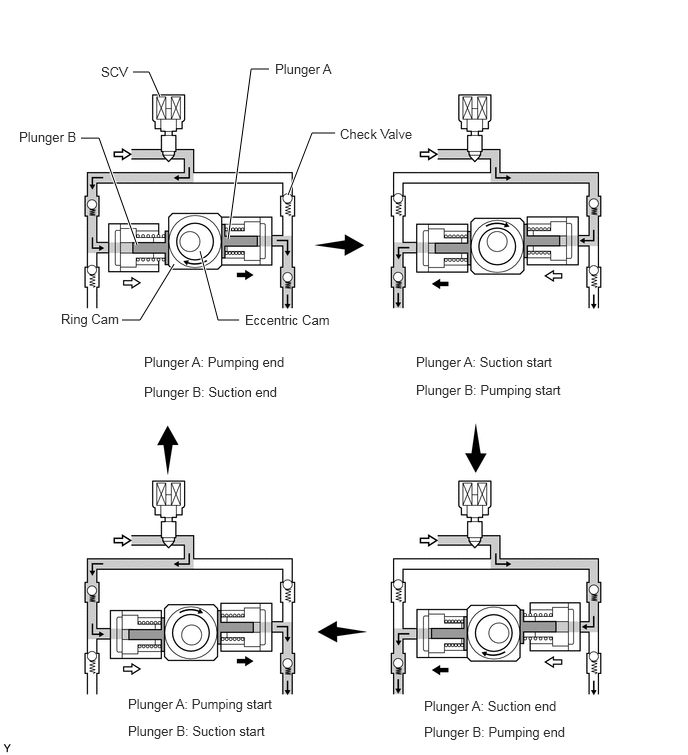
Due to the rotation of the eccentric cam, the ring cam pushes plunger A upward as illustrated below. The force of the spring pulls plunger B (which is located opposite plunger A) upward. As a result, plunger B draws fuel in, and plunger A pumps fuel at the same time.
1.427,2.552 1.031,1.438
1.031,1.438 0.844,1.438
true
3,2.031 3.25,1.385
3.25,1.385 3.49,1.385
true
2.375,2.49 2.615,0.719
2.615,0.719 2.802,0.719
true
1.667,1.01 1.552,0.75
1.552,0.75 1.385,0.75
true
1.813,2.75 1.458,3.333
1.458,3.333 1.271,3.333
true
2.083,2.615 2.271,3.333
2.271,3.333 2.49,3.333
true
1.052,0.667 1.552,1.073
0.5,0.406
10
SCV
2.865,0.635 3.656,1.021
0.792,0.385
10
Plunger A
0.198,1.344 0.99,1.729
0.792,0.385
10
Plunger B
3.542,1.313 4.469,1.698
0.927,0.385
10
Check Valve
0.635,3.24 1.427,3.604
0.792,0.365
10
Ring Cam
2.552,3.25 3.583,3.583
1.031,0.333
10
Eccentric Cam
1.5,3.688 3.208,4
1.708,0.313
10
Plunger A: Pumping end
4.333,3.688 6.042,4
1.708,0.313
10
Plunger A: Suction start
1.5,4 3.406,4.313
1.906,0.313
10
Plunger B: Suction end
4.333,3.979 6,4.25
1.667,0.271
10
Plunger B: Pumping start
1.333,7.25 3.042,7.563
1.708,0.313
10
Plunger A: Pumping start
1.333,7.531 3.24,7.844
1.906,0.313
10
Plunger B: Suction start
4.417,7.271 6.125,7.583
1.708,0.313
10
Plunger A: Suction end
4.417,7.542 6.083,7.813
1.667,0.271
10
Plunger B: Pumping end