Home › Engine / Hybrid System › 2AR-FE ENGINE CONTROL › SFI SYSTEM
NM3090E _51 Engine / Hybrid System _008626 2AR-FE ENGINE CONTROL _0048050 SFI SYSTEM DE DETAILS F

2AR-FE ENGINE CONTROL  SFI SYSTEM  DETAILS  KNOCK CONTROL SENSOR  


CONSTRUCTION


a.

In a conventional knock control sensor (resonant type), a vibration plate is built into the sensor. This plate has the same resonance point as the knocking* frequency of the engine block. This sensor can only detect vibrations in this frequency band.

HINT:

*: The term "knock" or "knocking" is used in this case to describe either preignition or detonation of the air fuel mixture in the combustion chamber. This preignition or detonation refers to the air fuel mixture being ignited earlier than is advantageous. This use of "knock" or "knocking" is not primarily used to refer to a loud mechanical noise that may be produced by an engine.


b.

A flat type knock control sensor (non-resonant type) has the ability to detect vibrations in a wider frequency band (from approximately 5 kHz to 15 kHz). The sensor has the following features:

·

The engine knocking frequency will vary slightly depending on the engine speed. The flat type knock control sensor can detect vibrations even when the engine knocking frequency changes. Due to the use of the flat type knock control sensor, the vibration detection ability has been increased compared to a conventional type knock control sensor, and more precise ignition timing control is possible.
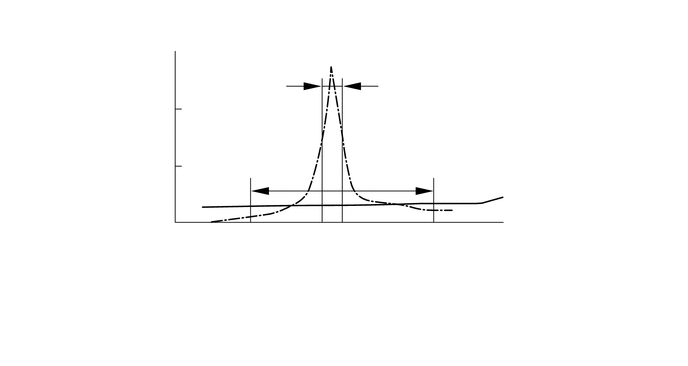
W100047
3.865,1.344 3.74,1.344 3.74,1.344 3.594,1.583 false 5.531,2.198 5.271,2.198 5.271,2.198 5.156,2.083 false 3.948,1.656 3.865,1.656 3.865,1.656 3.823,1.979 false 3.979,0.823 6.135,1.115 2.156,0.292 10 Detection Band of Resonant Type 3.969,1.573 5.781,1.844 1.813,0.271 10 Detection Band of Flat Type 3.125,2.354 3.906,2.625 0.781,0.271 10 Frequency 1.208,1.354 1.781,1.656 0.573,0.302 10 Voltage 1.583,0.469 1.823,0.656 0.24,0.188 10 (V) 5.115,2.375 5.438,2.667 0.323,0.292 10 (Hz) 3.906,1.26 4.094,1.448 0.188,0.188 10 *1 5.563,2.115 5.75,2.302 0.188,0.188 10 *2 0.208,3 4.115,3.313 3.906,0.313 10 *1: Resonance characteristic of conventional type (resonant) 0.198,3.365 3.854,3.698 3.656,0.333 10 *2: Resonance characteristic of flat type (non-resonant) 0.146,0.083 2.917,0.479 2.771,0.396 10 Characteristics of Knock Control Sensor


c.

A flat type knock control sensor is installed in an engine by placing it over the stud bolt installed on the cylinder block. For this reason, a hole for the stud bolt exists in the center of the sensor.


d.

In the sensor, a steel weight is located in the upper portion. An insulator is located between the weight and the piezoelectric element.


e.

An open/short circuit detection resistor is integrated in the sensor. When the ignition switch (engine switch*) is on (IG), the open/short circuit detection resistor in the knock control sensor and the resistor in the ECM keep the voltage at terminal KNK1 constant. An Integrated Circuit (IC) in the ECM constantly monitors the voltage of terminal KNK1. If the open/short circuit occurs between the knock control sensor and the ECM, the voltage of terminal KNK1 will change and the ECM will detect the open/short circuit and store a Diagnostic Trouble Code (DTC).

*: Models with entry and start system
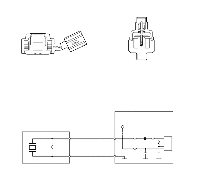

W100048
1.469,0.802 1.271,0.802 1.271,0.802 0.969,1.5 true 1,1.625 1.406,2.26 1.406,2.26 1.573,2.26 true 0.969,1.708 1.448,2.719 1.448,2.719 1.667,2.719 true 2.302,3.927 2.042,3.927 2.042,3.927 1.177,5.333 true 1.885,5.302 2.479,4.458 2.479,4.458 2.75,4.458 true 2.146,1.688 2.552,2.135 2.552,2.135 2.76,2.135 true 6.052,0.708 5.865,0.708 5.865,0.708 5.344,1.302 true 6.063,1.833 5.823,1.833 5.823,1.833 5.406,1.323 true 0.865,2.979 3.427,3.333 2.563,0.354 10 Flat Type (Non-resonant Type) 4.365,2.979 7.146,3.323 2.781,0.344 10 Conventional Type (Resonant Type) 6.094,1.75 7.135,2.094 1.042,0.344 10 Vibration Plate 6.104,0.625 7.052,1.25 0.948,0.625 10 Piezoelectric Element 1.719,2.635 3.125,2.969 1.406,0.333 10 Piezoelectric Element 2.354,3.854 3.854,4.146 1.5,0.292 10 Piezoelectric Element 2.813,2.052 4.229,2.635 1.417,0.583 10 Open/Short Circuit Detection Resistor 2.781,4.375 4.177,4.927 1.396,0.552 10 Open Circuit Detection Resistor 1.521,0.719 2.448,1.01 0.927,0.292 10 Steel Weight 1.615,2.167 2.25,2.417 0.635,0.25 10 Insulator 4.24,4.073 4.646,4.229 0.406,0.156 10 ECM 4.365,4.354 4.667,4.542 0.302,0.188 10 5 V 1.958,5.26 2.563,5.49 0.604,0.229 10 200 kΩ 4.542,4.74 5.146,4.969 0.604,0.229 10 200 kΩ 0.646,5.979 2.75,6.281 2.104,0.302 10 Flat Type Knock Control Sensor 6.052,5.115 6.24,5.302 0.188,0.188 10 IC 3.74,5.073 4.167,5.365 0.427,0.292 10 KNK1 3.74,5.688 4.167,5.99 0.427,0.302 10 EKNK


f.

Vibrations caused by knocking are transmitted to the steel weight. The inertia of this weight applies pressure to the piezoelectric element. This action generates electromotive force.

W100049
2.469,1.688 2.781,1.688 2.781,1.688 3.125,1.542 true 1.49,1.323 2.781,1.323 2.781,1.323 3.177,1.458 true 1.906,0.885 2.458,0.885 2.458,0.885 3.135,1.302 true 1.708,0.813 1.865,0.969 0.156,0.156 10 *1 1.333,1.219 1.5,1.406 0.167,0.188 10 *a 2.302,1.615 2.458,1.792 0.156,0.177 10 *2
*1 Steel Weight *2 Piezoelectric Element
*a Inertia - -


g.

To prevent water accumulation in the connecter, make sure to install the flat type knock control sensor in the position shown in the following illustration:

W111578
5.073,1.438 4.781,1.438 4.781,1.438 4.208,0.948 true 2.031,1.281 2.167,1.271 2.167,1.271 2.604,0.896 true 1.833,0.438 2.063,0.438 2.063,0.438 2.573,0.708 true 5.115,1.354 5.458,1.573 0.344,0.219 11 *1 1.802,1.219 2.146,1.438 0.344,0.219 11 10° 1.656,0.365 2,0.583 0.344,0.219 11 7°
*1 Knock Control Sensor - -