Home › Engine / Hybrid System › 2WW ENGINE CONTROL › ECD SYSTEM › from 2015.10
NM3090E _51 Engine / Hybrid System _043813 2WW ENGINE CONTROL _0205037 ECD SYSTEM DE DETAILS F

2WW ENGINE CONTROL  ECD SYSTEM  DETAILS  ACCELERATOR PEDAL POSITION SENSOR  


CONSTRUCTION


a.

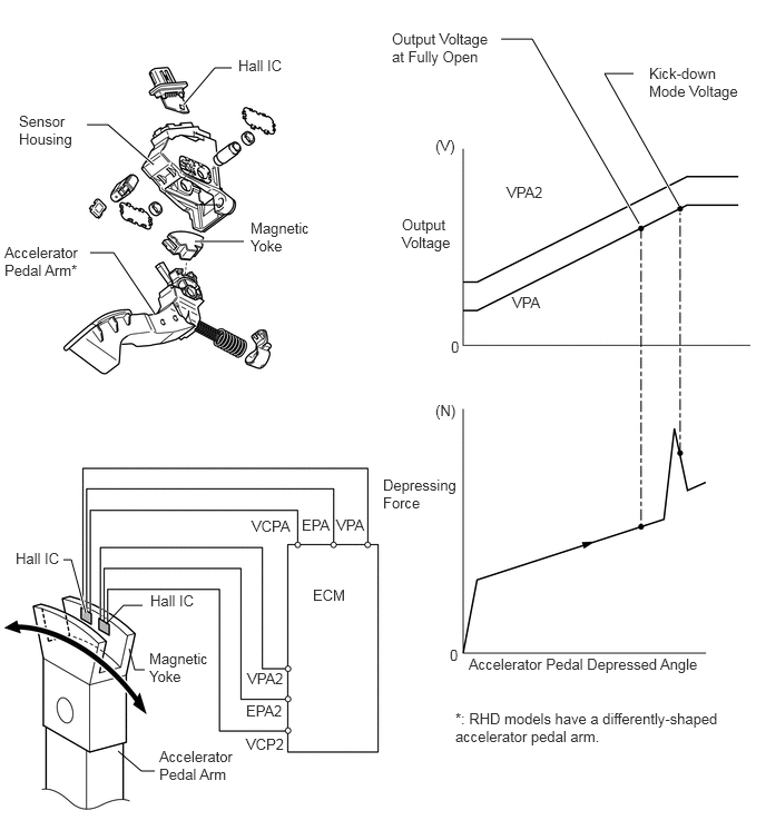
Models with Kick Down Mode

i.

The non-contact type accelerator pedal sensor assembly uses a Hall IC.


ii.

The magnetic yoke mounted at the base of the accelerator pedal arm moves around the Hall IC in accordance with the amount of effort applied to the accelerator pedal. The Hall IC converts the changes in the magnetic flux that occur into electrical signals, and outputs them in the form of accelerator pedal effort to the ECM.


iii.

This accelerator pedal sensor assembly includes 2 Hall ICs and circuits for the main and sub signals. Accelerator pedal sensor assembly converts the accelerator pedal depressed angles into electric signals with 2 differing characteristics and outputs them to the ECM.


iv.

When the depressing force applied to the accelerator pedal is greater than a predetermined amount, the ECM detects a "kick down on" from the VPA signal provided by the accelerator pedal sensor assembly.
W110778E03
0.594,5.24 0.667,5.24 0.667,5.24 0.802,5.74 true 1.333,5.667 1.156,5.667 1.156,5.667 0.99,5.844 false 2.167,0.635 2.01,0.635 2.01,0.635 1.719,0.979 true 0.813,1.167 1.01,1.167 1.01,1.167 1.438,1.542 true 0.844,2.365 1.063,2.365 1.063,2.365 1.448,2.938 true 2.063,1.917 1.823,1.917 false 1.208,6.073 1.26,6.271 1.26,6.271 1.354,6.271 false 1.104,7.031 1.323,7.219 1.323,7.219 1.448,7.219 false 6.354,1.927 5.656,0.688 5.656,0.688 5.927,0.688 true 5.979,2.094 4.979,0.365 4.979,0.365 4.688,0.365 true 1.823,2.26 2.281,2.26 true 4.208,6.052 4.365,6.229 0.156,0.177 10 false 0 2.229,0.531 2.75,0.906 0.521,0.375 10 false Hall IC 0.177,1.052 0.719,1.719 0.542,0.667 10 false Sensor Housing 0.042,2.281 0.771,3.042 0.729,0.76 10 false Accelerator Pedal Arm* 4.26,6.646 6.833,7.469 2.573,0.823 10 false *: RHD models have a differently-shaped accelerator pedal arm. 2.344,2.052 3.188,2.729 0.844,0.677 10 false Magnetic Yoke 3.76,2.021 4.375,2.708 0.615,0.688 10 false Output Voltage 4.74,1.719 5.198,2.115 0.458,0.396 10 false VPA2 4.792,2.75 5.25,3.146 0.458,0.396 10 false VPA 3.667,0.281 4.667,1.021 1,0.74 10 false Output Voltage at Fully Open 6.073,0.604 7.021,1.302 0.948,0.698 10 false Kick-down Mode Voltage 4.073,1.281 4.375,1.688 0.302,0.406 10 false (V) 4.219,3.167 4.365,3.51 0.146,0.344 10 false 0 4.073,3.76 4.344,4.063 0.271,0.302 10 false (N) 3.583,4.458 4.385,5.094 0.802,0.635 10 false Depressing Force 4.385,6.135 7.01,6.583 2.625,0.448 10 false Accelerator Pedal Depressed Angle 2.927,5.49 3.49,5.896 0.563,0.406 10 false ECM 0.146,5.146 0.656,5.563 0.51,0.417 10 false Hall IC 1.406,5.542 1.917,5.958 0.51,0.417 10 false Hall IC 1.396,6.083 2.063,6.74 0.667,0.656 10 false Magnetic Yoke 1.49,7 2.375,7.635 0.885,0.635 10 false Accelerator Pedal Arm 3.146,4.833 3.74,5.115 0.594,0.281 10 false VPA 2.823,4.833 3.292,5.083 0.469,0.25 10 false EPA 2.354,4.844 2.844,5.052 0.49,0.208 10 false VCPA 2.313,6.271 2.875,6.49 0.563,0.219 10 false VPA2 2.302,6.573 2.792,6.813 0.49,0.24 10 false EPA2 2.302,6.885 2.76,7.146 0.458,0.26 10 false VCP2


b.

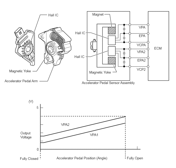
Models without Kick Down Mode

i.

The non-contact type accelerator pedal sensor assembly uses a Hall IC.


ii.

The magnetic yoke mounted at the accelerator pedal arm rotates around the Hall IC in accordance with the amount of effort applied to the accelerator pedal. The Hall IC converts the changes in the magnetic flux into electrical signals, and outputs them as accelerator pedal effort to the ECM.


iii.

The Hall IC contains circuits for the main and sub signals. The Hall IC converts the accelerator pedal depressed angles into electric signals with 2 differing characteristics and outputs them to the ECM.
W100142E24
1.167,1.948 1.635,0.604 1.635,0.604 1.917,0.604 true 2.229,2.583 1.938,3.313 1.938,3.313 1.604,3.313 true 4.552,1.115 4.469,0.583 4.469,0.583 4.25,0.583 true 4.438,1.583 3.698,1.333 3.698,1.333 3.5,1.333 true 4.427,2.063 3.688,2.313 3.688,2.313 3.49,2.313 true 2.052,2.052 1.49,2.906 1.49,2.906 1.323,2.906 true 4.625,2.667 4.75,2.938 4.75,2.938 4.583,2.938 true 3.333,3.292 5.604,3.74 2.271,0.448 10 false Accelerator Pedal Sensor Assembly 3.063,1.26 3.542,1.615 0.479,0.354 10 false Hall IC 3.76,0.5 4.302,0.896 0.542,0.396 10 false Magnet 3.031,2.229 3.51,2.583 0.479,0.354 10 false Hall IC 1.167,4.052 1.458,4.458 0.292,0.406 10 false (V) 1.49,4.302 1.615,4.635 0.125,0.333 10 false 5 0.833,5.344 1.417,6.063 0.583,0.719 10 false Output Voltage 1.5,6.01 1.625,6.302 0.125,0.292 10 false 0 0.813,6.385 1.667,6.74 0.854,0.354 10 false Fully Closed 5.167,6.365 5.917,6.698 0.75,0.333 10 false Fully Open 2.302,6.365 4.479,6.667 2.177,0.302 10 false Accelerator Pedal Position (Angle) 5.656,1.031 6.052,1.323 0.396,0.292 10 false VPA 5.656,1.375 6.052,1.667 0.396,0.292 10 false EPA 5.573,1.75 5.969,2.042 0.396,0.292 10 false VCPA 5.583,2.031 5.979,2.323 0.396,0.292 10 false VPA2 5.594,2.375 6.01,2.667 0.417,0.292 10 false EPA2 5.573,2.75 5.969,3.042 0.396,0.292 10 false VCP2 1.969,0.531 2.448,0.885 0.479,0.354 10 false Hall IC 3.667,5.417 4.063,5.708 0.396,0.292 10 false VPA1 2.49,5 2.885,5.292 0.396,0.292 10 false VPA2 6.281,1.885 6.656,2.198 0.375,0.313 10 false ECM 0.188,3.219 1.625,3.521 1.438,0.302 10 false Accelerator Pedal Arm 0.375,2.813 1.406,3.177 1.031,0.365 10 false Magnetic Yoke 3.635,2.865 4.667,3.229 1.031,0.365 10 false Magnetic Yoke