NM3090E
_52
Drivetrain
_008830
K111 MULTIDRIVE / CVT
_0059528
CVT SYSTEM
DE
DETAILS
F
K111 MULTIDRIVE / CVT CVT SYSTEM DETAILS TRANSMISSION CONTROL SWITCH
CONSTRUCTION
a.
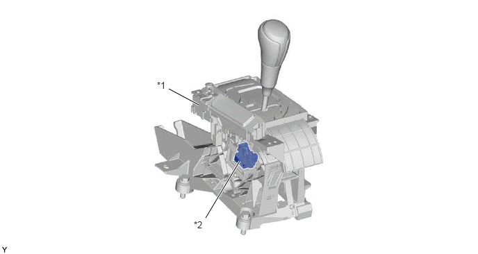
The transmission control switch is installed inside the shift lever assembly to detect whether the shift lever is in M (S signal) and the operating conditions of the shift lever "+" (upshift) or "-" (downshift).
2.531,1.333 2.979,1.573
true
3.083,3.271 3.594,2.417
true
2.354,1.198 2.667,1.396
0.313,0.198
10
false
*1
2.906,3.292 3.219,3.49
0.313,0.198
10
false
*2
| *1 | Shift Lever Assembly (Transmission Floor Shift Assembly) | *2 | Transmission Control Switch |
b.
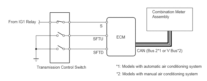
The transmission control switch sends the S, SFTU and SFTD signals to the ECM. The ECM also sends the selected shift range position signal to the combination meter assembly via CAN.
4.74,1.667 6.479,1.958
1.74,0.292
10
false
CAN (Bus 2*1 or V Bus*2)
4.031,1.198 4.49,1.396
0.458,0.198
10
false
ECM
5.271,0.323 6.458,1.01
1.188,0.688
10
false
Combination Meter Assembly
3.458,0.813 3.625,1.01
0.167,0.198
10
false
S
3.219,1.26 3.646,1.469
0.427,0.208
10
false
SFTU
3.229,1.729 3.646,1.927
0.417,0.198
10
false
SFTD
1.271,2.24 3.49,2.708
2.219,0.469
10
false
Transmission Control Switch
0.292,0.667 1.323,1.135
1.031,0.469
10
false
From IG1 Relay
4.021,2.208 7.094,2.458
3.073,0.25
10
false
*1: Models with automatic air conditioning system
4.031,2.469 7.021,2.719
2.99,0.25
10
false
*2: Models with manual air conditioning system