1AD-FTV EMISSION CONTROL EMISSION CONTROL SYSTEM ON-VEHICLE INSPECTION
CAUTION / NOTICE / HINT
- HINT:
-
When there is a malfunction which causes the EGR system to remain on, black or white smoke may be emitted from the exhaust pipe.
PROCEDURE

 1.CHECK SEATING OF EGR VALVE
Check that the engine starts and idles.
Stop the engine.
2.CHECK EGR VALVE OPERATION
Connect the GTS to the DLC3.
Turn the ignition switch to ON and turn the GTS on.
Enter the following menus: Powertrain / Engine / Active Test / Control the EGR Step Position.
- Powertrain > Engine > Active Test
-
Tester Display Control the EGR Step Position - 50004 61 95
Check the Data List.
Enter the following menus: Powertrain / Engine / Data List / Target EGR Position and Actual EGR Valve Pos.
- Powertrain > Engine > Data List
-
Tester Display Target EGR Position Actual EGR Valve Pos. - 50003 61 59,578
- OK:
Control Range Condition Specified Condition Active Test performed (Set EGR position to 0% → 30% → 60% → 90% → 60% → 30% → 0%) Actual EGR valve opening percentage changes according to Active Test operation
If the result is not as specified, refer to DTC P042E.
Click hereEngine / Hybrid System>1AD-FTV ENGINE CONTROL>ECD SYSTEM>P042E
25630
3.CHECK NO. 2 EGR VALVE ASSEMBLY
Disconnect the vacuum transmitting hose from the No. 2 EGR valve assembly.
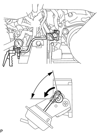
| *1 | No. 2 EGR Valve Assembly |
| *2 | Rod |
Apply vacuum and check that the rod of the No. 2 EGR valve assembly operates as shown in the illustration.
If the rod does not operate, replace the No. 2 EGR valve assembly.
Click hereEngine / Hybrid System>1AD-FTV EMISSION CONTROL>EGR COOLER>REMOVAL
4.VISUALLY INSPECT HOSES, CONNECTIONS AND GASKETS
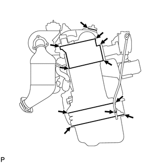
Visually check that the hoses, connections and gaskets have no cracks, leaks or damage.
- NOTICE:
- ·
Detachment or other problems with the engine oil level dipstick, oil filler cap sub-assembly, PCV hose or other components may cause the engine to run improperly.
·Air suction caused by disconnections, looseness or cracks in the parts of the air induction system between the diesel throttle body assembly and cylinder head will cause engine failure or engine malfunctions.
If the result is not as specified, replace parts as necessary.