3ZR-FE STARTING STARTER(for 1.0 kW Type) REASSEMBLY
PROCEDURE

 28021
1.INSTALL STARTER CENTER BEARING CLUTCH SUB-ASSEMBLY
Apply high-temperature grease to the bushing and spline of the starter center bearing clutch sub-assembly and stop collar.
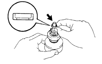
Place the starter center bearing clutch sub-assembly and stop collar on the planetary shaft.
Apply high-temperature grease to the snap ring and install it onto the planetary shaft groove.
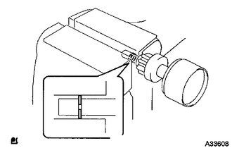
Using a vise, compress the snap ring.
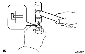
Hold the starter center bearing clutch sub-assembly, tap the planetary shaft, and install the stop collar onto the snap ring with a plastic-faced hammer.
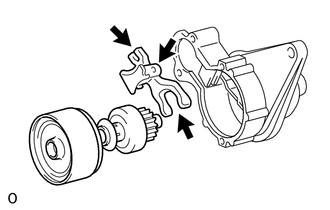
Apply high-temperature grease to the drive lever which is in contact with the starter assembly pivot part of the drive lever.
Install the drive lever onto the starter center bearing clutch sub-assembly.
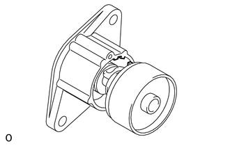
| *1 | Cutout |
| *2 | Protrusion |
Align the protrusion of the shock absorber with the cutout of the starter drive housing assembly and install it.
28160
2.INSTALL STARTER ARMATURE ASSEMBLY
Install the starter armature assembly to the starter yoke assembly.
28140
3.INSTALL STARTER BRUSH HOLDER ASSEMBLY
Install the starter brush holder assembly.
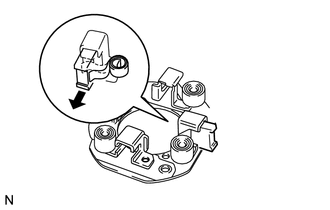
for Brush Holder Side:
Push out the 2 brushes from the starter brush holder assembly so that they are held in place by the springs as shown in the illustration.
Install the starter brush holder assembly to the starter armature assembly and push in the 2 brushes.
for Starter Yoke Side:
Using a screwdriver, pry the springs and connect the 2 brushes to the starter brush holder assembly.
Apply high-temperature grease with additives to the bearing of the starter commutator end frame assembly.
Install the starter commutator end frame assembly with the 2 screws.
- Torque:
- 1.5 N*m (15 kgf*cm, 13 in.*lbf)
- NOTICE:
-
To avoid interference between the starter brush holder assembly and dust protector, push the starter commutator end frame assembly on at an angle.
28120
4.INSTALL STARTER YOKE ASSEMBLY
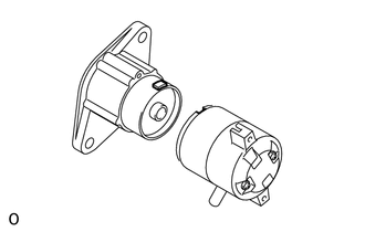
| *1 | Cutout |
| *2 | Protrusion |
Align the cutout of the starter yoke assembly with the protrusion of the shock absorber.
Install the starter yoke assembly and starter armature assembly with the 2 through bolts.
- Torque:
- 5.9 N*m (60 kgf*cm, 52 in.*lbf)
28150
5.INSTALL MAGNET STARTER SWITCH ASSEMBLY
Hang the plunger of the magnet starter switch assembly onto the drive lever from the upper side.
Install the magnet starter switch assembly with the 2 nuts.
- Torque:
- 8.3 N*m (85 kgf*cm, 73 in.*lbf)
Connect the lead wire to terminal C with the nut.
- Torque:
- 9.8 N*m (100 kgf*cm, 87 in.*lbf)