RM3090E
_55
Steering
_008772
POWER ASSIST SYSTEMS
_0049011
POWER STEERING SYSTEM
U
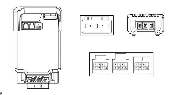
POWER ASSIST SYSTEMS POWER STEERING SYSTEM TERMINALS OF ECU
CHECK POWER STEERING ECU ASSEMBLY
3.729,0.198 4.052,0.396
0.323,0.198
5.719,0.198 6.042,0.396
0.323,0.198
3.906,1.844 4.229,2.042
0.323,0.198
4.708,1.844 5.031,2.042
0.323,0.198
5.563,1.844 5.885,2.042
0.323,0.198
1.875,0.833 2.198,1.031
0.323,0.198
0.719,1.313 1.042,1.51
0.323,0.198
1.104,1.313 1.427,1.51
0.323,0.198
1.479,1.313 1.802,1.51
0.323,0.198
0.708,3.469 1.031,3.667
0.323,0.198
0.906,1.313 1.031,1.146
false
1.271,1.313 1.292,1.146
false
1.625,1.313 1.542,1.146
false
2.021,0.833 2.021,0.771
false
1.031,3.594 1.083,3.49
false
3.823,0.229 4.219,0.729
0.396,0.5
10
h2
5.854,0.198 6.302,0.563
0.448,0.365
10
c
3.99,1.875 4.563,2.344
0.573,0.469
10
h1
4.833,1.854 5.323,2.219
0.49,0.365
10
a
5.688,1.854 6.135,2.24
0.448,0.385
10
b
0.146,0.083 0.427,0.313
0.281,0.229
10
*a
1.969,0.875 2.479,1.219
0.51,0.344
10
h2
0.802,1.344 1.25,1.698
0.448,0.354
10
h1
1.219,1.313 1.604,1.646
0.385,0.333
10
a
1.604,1.313 2.083,1.792
0.479,0.479
10
b
0.844,3.49 1.094,3.635
0.25,0.146
10
c
| *a | Component with harness connected
(Power Steering ECU Assembly) |
- | - |
a.
Measure the voltage and resistance according to the value(s) in the table below.
- NOTICE:
-
When the power steering warning light is illuminated due to a malfunction, the fail-safe function may cause the voltage of the power steering ECU assembly terminals to become 0 V.
| Terminal No. (Symbol) | Wiring Color | Terminal Description | Condition | Specified Condition |
|---|---|---|---|---|
| h1-1 (IG) - h2-2 (PGND) | R - R | IG power source | Ignition switch ON | 11 to 14 V |
| h1-4 (CANH) - h1-8 (CANL) | W - B | CAN communication line | Ignition switch off | 54 to 69 Ω |
| h1-5 (TS) - h2-2 (PGND) | O - R | Terminal TS of DLC3 | Always | 11 to 14 V |
| a-1 (TRQG) - Body ground | - (Not available) - Body ground | Torque sensor ground | Always | Below 1 Ω |
| a-2 (TRQ2) - a-1 (TRQG) | - (Not available) | Torque sensor signal | Engine running Steering wheel not being turned (without load) | 2.3 to 2.7 V |
| Engine running Steering wheel being turned to right with vehicle stopped | 0.3 to 2.5 V | |||
| Engine running Steering wheel being turned to left with vehicle stopped | 2.5 to 4.7 V | |||
| a-3 (TRQV) - a-1 (TRQG) | - (Not available) | Torque sensor voltage source | Engine running | 8.5 to 10.5 V |
| a-5 (TRQF) - a-1 (TRQG) | - (Not available) | Torque sensor reference voltage | Engine running | 3.35 to 3.37 V |
| a-7 (TRQ1) - a-1 (TRQG) | - (Not available) | Torque sensor signal | Engine running Steering wheel not being turned (without load) | 2.3 to 2.7 V |
| Engine running Steering wheel being turned to right with vehicle stopped | 2.5 to 4.7 V | |||
| Engine running Steering wheel being turned to left with vehicle stopped | 0.3 to 2.5 V | |||
| b-1 (RZCS2) - h2-2 (PGND) | B - R | Rotation angle sensor COS aspect output signal | Engine running Steering wheel turned | 0.68 to 4.42 V |
| b-2 (RZV2) - h2-2 (PGND) | G - R | Rotation angle sensor excitation output signal | Engine running Steering wheel turned | 0.68 to 4.42 V |
| b-3 (RZSN2) - h2-2 (PGND) | L - R | Rotation angle sensor SIN aspect output signal | Engine running Steering wheel turned | 0.68 to 4.42 V |
| b-5 (RZCS1) - h2-2 (PGND) | R - R | Rotation angle sensor COS aspect output signal | Engine running Steering wheel turned | 0.68 to 4.42 V |
| b-6 (RZV1) - h2-2 (PGND) | W - R | Rotation angle sensor excitation output signal | Engine running Steering wheel turned | 0.68 to 4.42 V |
| b-7 (RZSN1) - h2-2 (PGND) | Y - R | Rotation angle sensor SIN aspect output signal | Engine running Steering wheel turned | 0.68 to 4.42 V |
| h2-1 (PIG) - h2-2 (PGND) | R - R | Power source | Always | 11 to 14 V |
| h2-2 (PGND) - Body ground | R - Body ground | Power ground | Always | Below 1 Ω |
| c-1 (PHA) - h2-2 (PGND) | # - R | A phase motor output | Engine running Steering wheel turned | Value changes within 4 to 35 V range |
| c-2 (PHB) - h2-2 (PGND) | # - R | B phase motor output | Engine running Steering wheel turned | Value changes within 4 to 35 V range |
| c-3 (PHC) - h2-2 (PGND) | # - R | C phase motor output | Engine running Steering wheel turned | Value changes within 4 to 35 V range |
- HINT:
-
# means that the motor terminal is tightened directly to the ECU with bolts.