RM3090E
_58
Vehicle Interior
_008789
HEATING / AIR CONDITIONING
_0049438
COMBUSTION TYPE POWER HEATER SYSTEM
C
HEATING / AIR CONDITIONING COMBUSTION TYPE POWER HEATER SYSTEM 010 Over Voltage Shutoff 011 Under Voltage Shutoff
DESCRIPTION
| DTC No. | Detection Item | DTC Detection Condition | Trouble Area |
|---|---|---|---|
| 010 | Over Voltage Shutoff | Battery voltage is 14 V or more for 20 seconds or more. | ·
Harness or connector ·
Battery ·
Generator assembly ·
Heater assembly |
| 011 | Under Voltage Shutoff | Battery voltage is 10 V or less for 20 seconds or more. | ·
Harness or connector ·
Battery ·
Generator assembly ·
Heater assembly |
WIRING DIAGRAM
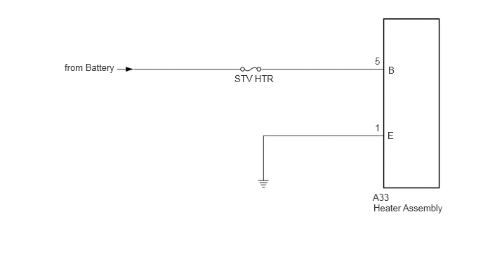
0.958,0.917 1.833,1.167
0.875,0.25
10
from Battery
3.479,1.083 4.354,1.333
0.875,0.25
10
STV HTR
5.563,0.823 5.76,1.042
0.198,0.219
10
5
5.563,1.813 5.76,2.031
0.198,0.219
10
1
5.75,1.927 5.948,2.146
0.198,0.219
10
E
5.76,0.958 6.281,1.219
0.521,0.26
10
B
5.531,2.844 6.052,3.104
0.521,0.26
10
A33
5.542,3 6.729,3.302
1.188,0.302
10
Heater Assembly
CAUTION / NOTICE / HINT
- NOTICE:
-
Inspect the fuses for circuits related to this system before performing the following inspection procedure.
- HINT:
-
Before performing the following inspection procedure, check the battery and generator assembly and confirm that they are operating normally.
PROCEDURE
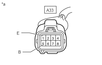
1.CHECK HARNESS AND CONNECTOR (HEATER ASSEMBLY - BATTERY AND BODY GROUND)
a.
1.5,0.208 1.896,0.448
0.396,0.24
1.458,1.5 1.031,1.75
1.031,1.75 0.76,1.75
true
1.448,1.208 0.99,1.104
0.99,1.104 0.719,1.104
true
1.563,0.26 2.021,0.458
0.458,0.198
10
A33
0.052,0.052 0.51,0.25
0.458,0.198
10
*a
0.563,1.031 0.75,1.229
0.188,0.198
10
E
0.615,1.667 0.823,1.875
0.208,0.208
10
B
| *a | Front view of wire harness connector
(to Heater assembly) |
Disconnect the heater assembly connector.
b.
Measure the voltage according to the value(s) in the table below.
- Standard Voltage:
Tester Connection Condition Specified Condition A33-5 (B) - Body ground Always 11 to 14 V
c.
Measure the resistance according to the value(s) in the table below.
- Standard Resistance:
Tester Connection Condition Specified Condition A33-1 (E) - Body ground Always Below 1 Ω
- Result:
Proceed to OK NG
OK
REPLACE HEATER ASSEMBLY
NG
REPAIR OR REPLACE HARNESS OR CONNECTOR