RM3090E
_58
Vehicle Interior
_008429
LIGHTING (INT)
_0050310
BACK DOOR COURTESY SWITCH
G
LIGHTING (INT) BACK DOOR COURTESY SWITCH INSPECTION
PROCEDURE

 69350
1.INSPECT BACK DOOR LOCK ASSEMBLY (BACK DOOR COURTESY SWITCH)
a.
1.948,1.656 2.417,1.427
true
2.583,1.406 2.969,1.25
true
1.292,1.563 1.698,1
true
0.792,1.552 0.469,1.333
true
0.417,2.333 1.01,1.813
true
2.573,1.271 2.969,0.615
true
2.438,1.26 1.781,0.479
true
0.073,0.031 0.385,0.188
0.313,0.156
10
*a
1.635,0.844 1.948,1
0.313,0.156
10
*b
0.323,1.188 0.635,1.344
0.313,0.156
10
*c
0.25,2.271 0.563,2.427
0.313,0.156
10
*d
1.969,2.688 2.281,2.844
0.313,0.156
10
*e
1.917,2.885 2.229,3.042
0.313,0.156
10
*f
1.781,3.5 2.063,3.76
0.281,0.26
10
*g
1.5,3.906 1.813,4.063
0.313,0.156
10
*h
3.01,1.156 3.344,1.344
0.333,0.188
10
CTY
1.823,1.594 1.979,1.792
0.156,0.198
10
E
1.656,0.313 1.99,0.5
0.333,0.188
10
M-
2.927,0.427 3.26,0.615
0.333,0.188
10
M+
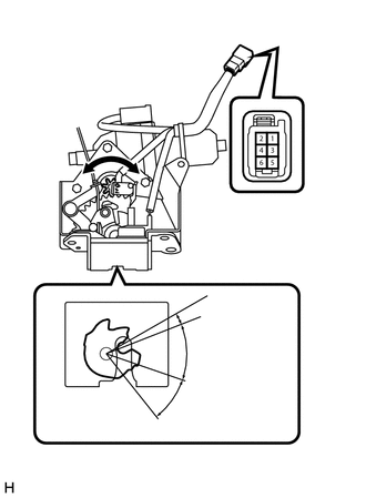
| *a | Component without harness connected
(Back Door Lock Assembly (Back Door Courtesy Switch)) |
| *b | Clockwise |
| *c | Counterclockwise |
| *d | Drive Gear |
| *e | Over-latch |
| *f | Full-latch |
| *g | Half-latch |
| *h | Open-latch |
w/ Power Back Door:
i.
Apply battery voltage to the door lock motor and check the operation of the door lock motor.
- OK:
Condition Specified Condition Battery positive (+) → Terminal 1 (M+)
Battery negative (-) → Terminal 2 (M-)Latch turns to full-latch position (clockwise rotation) Battery positive (+) → Terminal 2 (M-)
Battery negative (-) → Terminal 1 (M+)Latch turns to open-latch position (counterclockwise rotation)
ii.
Measure the resistance according to the value(s) in the table below.
- Standard Resistance:
Tester Connection Condition Specified Condition 3 (CTY) - 4 (E) Over-latch 10 kΩ or higher 3 (CTY) - 4 (E) Full-latch 10 kΩ or higher 3 (CTY) - 4 (E) Half-latch 10 kΩ or higher 3 (CTY) - 4 (E) Open-latch Below 1 Ω
If the result is not as specified, replace the back door lock assembly (back door courtesy switch).
b.
1.927,3.719 2.271,4.031
true
1.729,3.74 1.76,4.115
true
1.552,3.74 1.198,4.042
true
0.958,3.052 1.271,3.208
0.313,0.156
10
*a
2.573,1.927 2.885,2.083
0.313,0.156
10
*b
2.615,0.979 2.927,1.135
0.313,0.156
10
*c
1.073,4.063 1.385,4.26
0.313,0.198
10
D+
1.625,4.135 2.24,4.333
0.615,0.198
10
ACT+
2.208,4.052 2.823,4.25
0.615,0.198
10
ACT-
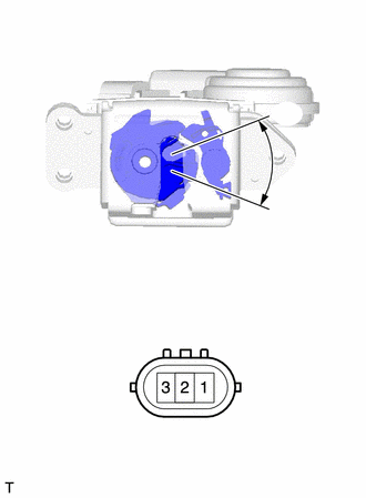
| *a | Component without harness connected
(Back Door Lock Assembly (Back Door Courtesy Switch)) |
| *b | Unlock |
| *c | Lock |
w/o Power Back Door:
i.
Move the back door lock assembly to the lock position.
ii.
Apply battery voltage to the door lock motor and check the operation of the door lock motor.
- OK:
Condition Specified Condition Battery positive (+) → Terminal 2 (ACT+)
Battery negative (-) → Terminal 1 (ACT-)Unlock
iii.
Measure the resistance according to the value(s) in the table below.
- Standard Resistance:
Tester Connection Condition Specified Condition 3 (D+) - 1 (ACT-) Lock 10 kΩ or higher 3 (D+) - 1 (ACT-) Unlock Below 1 Ω
If the result is not as specified, replace the back door lock assembly (back door courtesy switch).