RM3090E
_59
Vehicle Exterior
_008795
WIPER / WASHER
_0050248
WIPER AND WASHER SYSTEM(w/ Rain Sensor)
J
WIPER / WASHER WIPER AND WASHER SYSTEM(w/ Rain Sensor) Power Source Circuit
DESCRIPTION
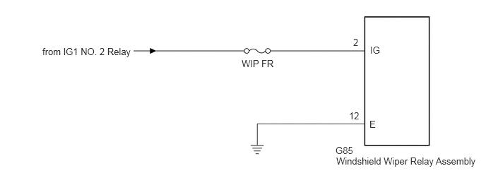
This circuit provides power to the windshield wiper relay assembly.
WIRING DIAGRAM
0.625,0.677 3.688,0.875
3.063,0.198
10
from IG1 NO. 2 Relay
3.563,0.854 4.479,1.052
0.917,0.198
10
WIP FR
4.948,2.135 5.865,2.333
0.917,0.198
10
G85
4.958,2.292 7.083,2.604
2.125,0.313
10
Windshield Wiper Relay Assembly
5.146,1.625 5.458,1.823
0.313,0.198
10
12
5.208,0.542 5.521,0.74
0.313,0.198
10
2
5.458,0.656 5.771,0.854
0.313,0.198
10
IG
5.448,1.75 5.604,1.948
0.156,0.198
10
E
CAUTION / NOTICE / HINT
- NOTICE:
-
Inspect the fuses for circuits related to this system before performing the following inspection procedure.
PROCEDURE
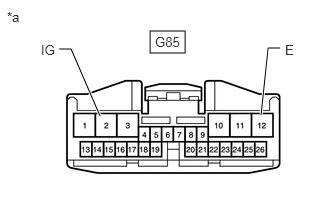
1.CHECK HARNESS AND CONNECTOR (WINDSHIELD WIPER RELAY ASSEMBLY - BATTERY AND BODY GROUND)
a.
1.563,0.323 1.927,0.552
0.365,0.229
1.042,1.208 0.74,0.51
0.74,0.51 0.615,0.51
true
2.719,1.198 2.792,0.5
2.792,0.5 2.917,0.5
true
0.073,0.094 0.385,0.292
0.313,0.198
10
*a
1.615,0.354 2.073,0.552
0.458,0.198
10
G85
0.427,0.438 0.74,0.635
0.313,0.198
10
IG
2.969,0.438 3.281,0.635
0.313,0.198
10
E
| *a | Front view of wire harness connector
(to Windshield Wiper Relay Assembly) |
Disconnect the windshield wiper relay assembly connector.
b.
Measure the resistance according to the value(s) in the table below.
- Standard Resistance:
Tester Connection Condition Specified Condition G85-12 (E) - Body ground Always Below 1 Ω
c.
Measure the voltage according to the value(s) in the table below.
- Standard Voltage:
Tester Connection Switch Condition Specified Condition G85-2 (IG) - Body ground Ignition switch ON 11 to 14 V Ignition switch off Below 1 V
- Result:
Proceed to OK NG
OK
PROCEED TO NEXT SUSPECTED AREA SHOWN IN PROBLEM SYMPTOMS TABLE
Click hereVehicle Exterior>WIPER / WASHER>WIPER AND WASHER SYSTEM(w/ Rain Sensor)>PROBLEM SYMPTOMS TABLE
NG
REPAIR OR REPLACE HARNESS OR CONNECTOR