RM3090E
_56
Audio / Visual / Telematics
_008432
PARK ASSIST / MONITORING
_0050793
CLEARANCE SONAR MAIN SWITCH
G
PARK ASSIST / MONITORING CLEARANCE SONAR MAIN SWITCH INSPECTION
PROCEDURE

 83950M
1.INSPECT TELLTALE LIGHT ASSEMBLY (CLEARANCE SONAR MAIN SWITCH)
a.
2.479,1.021 2.823,0.438
true
1.344,1.021 1.042,0.323
true
0.104,0.094 0.417,0.292
0.313,0.198
10
*a
2.885,0.323 3.229,0.5
0.344,0.177
10
ECU
0.917,0.146 1.396,0.385
0.479,0.24
10
LAPB
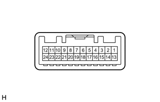
| *a | Component without harness connected
(Telltale Light Assembly (Clearance Sonar Main Switch)) |
Measure the resistance according to the value(s) in the table below.
- Standard Resistance:
Tester Connection Switch Condition Specified Condition 1 (ECU) - 9 (LAPB) Clearance sonar main switch off 10 kΩ or higher Clearance sonar main switch on Below 1 Ω
If the result is not as specified, replace the telltale light assembly (clearance sonar main switch).
b.
1.427,1.885 1.76,1.271
true
2.198,1.01 2.292,0.375
true
2.052,1.01 1.979,0.396
true
1.885,1.021 1.625,0.438
true
1.354,1.031 1.042,0.448
true
2.76,1.823 2.448,1.271
true
2.323,1.021 2.646,0.417
true
2.625,0.229 2.865,0.417
0.24,0.188
10
RL
0.104,0.094 0.417,0.292
0.313,0.198
10
*a
2.219,0.198 2.458,0.385
0.24,0.188
10
BK
1.479,0.24 1.719,0.427
0.24,0.188
10
OP
0.844,0.271 1.25,0.469
0.406,0.198
10
LAPB
1.844,0.219 2.083,0.406
0.24,0.188
10
RR
2.75,1.844 2.906,2.063
0.156,0.219
10
E
1.292,1.885 1.625,2.042
0.333,0.156
10
DIM
| *a | Component without harness connected
(Telltale Light Assembly (Clearance Sonar Main Switch)) |
Check that the switch illuminates.
i.
Apply battery voltage to the telltale lightassembly (clearance sonar main switch) and check that the switch illuminates.
- OK:
Connection Specified Condition Battery positive (+) → Terminal 9 (LAPB)
Battery negative (-) → Terminal 2 (RL)Illuminates Battery positive (+) → Terminal 9 (LAPB)
Battery negative (-) → Terminal 3 (BK)Illuminates Battery positive (+) → Terminal 9 (LAPB)
Battery negative (-) → Terminal 4 (RR)Illuminates Battery positive (+) → Terminal 9 (LAPB)
Battery negative (-) → Terminal 5 (OP)Illuminates Battery positive (+) → Terminal 9 (LAPB)
Battery positive (+) → Terminal 18 (DIM)
Battery negative (-) → Terminal 2 (RL)
Battery negative (-) → Terminal 13 (E)Illuminates in dimmed state Battery positive (+) → Terminal 9 (LAPB)
Battery positive (+) → Terminal 18 (DIM)
Battery negative (-) → Terminal 3 (BK)
Battery negative (-) → Terminal 13 (E)Illuminates in dimmed state Battery positive (+) → Terminal 9 (LAPB)
Battery positive (+) → Terminal 18 (DIM)
Battery negative (-) → Terminal 4 (RR)
Battery negative (-) → Terminal 13 (E)Illuminates in dimmed state Battery positive (+) → Terminal 9 (LAPB)
Battery positive (+) → Terminal 18 (DIM)
Battery negative (-) → Terminal 5 (OP)
Battery negative (-) → Terminal 13 (E)Illuminates in dimmed state
If the result is not as specified, replace the telltale light assembly (clearance sonar main switch).