EA64F MANUAL TRANSMISSION / TRANSAXLE TRANSMISSION CONTROL CABLE ADJUSTMENT
PROCEDURE

 33820B
1.ADJUST TRANSAXLE CONTROL CABLE ASSEMBLY
- HINT:
- ·
After the shift lever or the shift cable is replaced, be sure to adjust the transmission control cable assembly.
·If the shift lever does not move (or the shift lever is difficult to move) to the 1st or 2nd position, or if it is possible to move the shift lever to the reverse position without pulling up the slider shaft, the length of the cable must be adjusted.
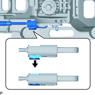
| *1 | Case |
| *2 | Lock Piece |
| *3 | Slider |
| *a | Lock Release Condition |
| *b | Lock Condition |
| *c | Pull |
To release the lock (lock condition to lock release condition).
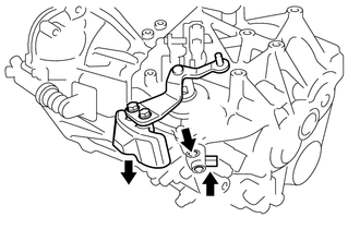
Pressing the shift and select lever shaft (*1) and pin (*2), push in pin (*3) and check that the shift and select lever shaft is secured at the 1st-2nd gear selected position (the shaft comes to a stop at the position 8 mm (0.31 in.) below the N position).
Remove the stopper pin, release the lock, and reinsert the stopper pin.
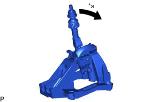
| *a | Reverse Direction |
Turn the shift lever in the reverse direction without pulling up the slider shaft.
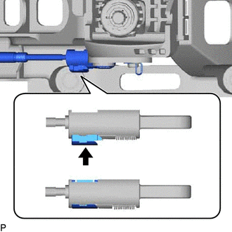
| *1 | Case |
| *2 | Lock Piece |
| *3 | Slider |
| *a | Lock Release Condition |
| *b | Lock Condition |
| *c | Push |
While holding the shift lever in the reverse direction, lock the cable length adjustment mechanism of the select cable.
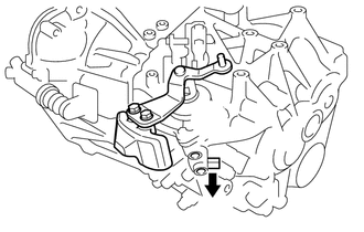
| *a | Pull |
Release the shift and select lever shaft straight pin that fixes the shift and select lever assembly.
Pull the pin toward the left front side of the vehicle.
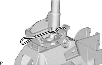
for new shift lever:
Remove the stopper pin and dispose of it.