Home › Engine / Hybrid System › 2AD-FHV ENGINE CONTROL › ECD SYSTEM
RM3090E _51 Engine / Hybrid System _008730 2AD-FHV ENGINE CONTROL _0049704 ECD SYSTEM C

2AD-FHV ENGINE CONTROL  ECD SYSTEM  P0617  Starter Relay Circuit High  


DESCRIPTION

While the engine is being cranked, positive battery voltage is applied to terminal STA of the ECM.

If the ECM detects the starter control (STA) signal while the vehicle is being driven, it determines that there is a malfunction in the STA circuit. The ECM then illuminates the MIL and stores the DTC.

This monitor runs when the vehicle has been driven at 20 km/h (12.5 mph) or more for more than 20 seconds.

DTC No. Detection Item DTC Detection Condition Trouble Area MIL Memory
P0617 Starter Relay Circuit High Conditions (a), (b) and (c) are met for 20 seconds
(a) Vehicle speed is more than 20 km/h (12.5 mph).
(b) Engine speed is more than 1000 rpm.
(c) STA signal is on.
(1 trip detection logic)
·

ST relay circuit

·

Park/neutral position switch assembly


Comes on DTC stored

Related Data List
DTC No. Data List
P0617 Starter Signal

CONFIRMATION DRIVING PATTERN

DTC No. DTC Detection Drive Pattern
P0617 Drive vehicle for 25 seconds or more at a speed of 20 km/h (12.5 mph) or more and an engine speed of 1000 rpm or higher

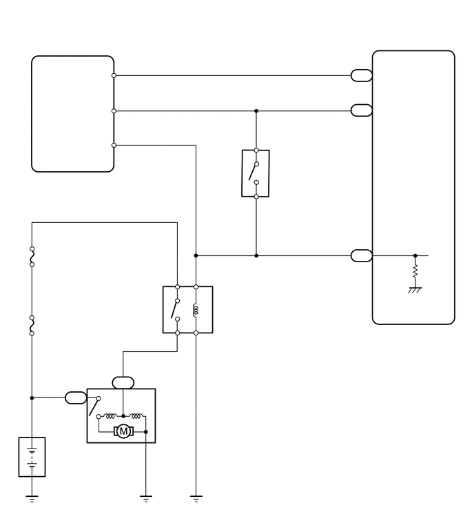
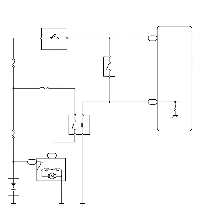
WIRING DIAGRAM

A284209
0.104,0.094 4.521,0.573 4.417,0.479 12 false w/ Entry and Start System: 0.198,2.625 2.51,3.177 2.313,0.552 10 false Certification ECU (Smart Key ECU Assembly) 0.188,2.438 0.646,2.635 0.458,0.198 10 false G82 1.271,1.594 1.938,1.875 0.667,0.281 10 false STAR 1.438,1.063 1.802,1.323 0.365,0.26 10 false NE 1.375,2.104 2.042,2.385 0.667,0.281 10 false STA 1.75,0.948 2.073,1.198 0.323,0.25 10 false 16 1.781,1.5 2.104,1.75 0.323,0.25 10 false 5 1.792,2 2.115,2.25 0.323,0.25 10 false 7 5.344,1.052 5.667,1.302 0.323,0.25 10 false A61 5.375,1.406 5.698,1.656 0.323,0.25 10 false 38 5.354,3.781 5.677,4.031 0.323,0.25 10 false A61 5.344,1.583 5.667,1.833 0.323,0.25 10 false B76 5.375,3.573 5.698,3.823 0.323,0.25 10 false 43 5.688,3.667 6.354,3.948 0.667,0.281 10 false STA 5.688,1.583 6.354,1.865 0.667,0.281 10 false NSW 5.688,1.052 6.354,1.333 0.667,0.281 10 false NEO 6.104,5.01 6.771,5.292 0.667,0.281 10 false ECM 3.271,4.542 3.719,4.833 0.448,0.292 10 false ST 0.563,3.781 1.01,4.073 0.448,0.292 10 false ST 0.563,4.865 1.458,5.198 0.896,0.333 10 false FL MAIN 1.51,6.74 2.406,7.073 0.896,0.333 10 false Starter 0.719,6.771 1.615,7.104 0.896,0.333 10 false Battery 1.031,5.917 1.375,6.177 0.344,0.26 10 false C4 1.76,5.698 2.104,5.958 0.344,0.26 10 false B6 1.125,5.719 1.448,5.969 0.323,0.25 10 false 1 1.604,5.698 1.927,5.948 0.323,0.25 10 false 1 3.083,5.073 3.406,5.323 0.323,0.25 10 false 1 3.052,4.104 3.375,4.354 0.323,0.25 10 false 2 2.521,4.104 2.844,4.354 0.323,0.25 10 false 5 2.5,5.063 2.823,5.313 0.323,0.25 10 false 3 4.177,2.24 4.5,2.49 0.323,0.25 10 false B36 4.135,2.448 5.208,3.615 1.073,1.167 10 false Park/Neutral Position Switch Assembly 3.698,2.052 4.021,2.302 0.323,0.25 10 false 4 3.698,2.99 4.021,3.24 0.323,0.25 10 false 9 5.375,0.885 5.698,1.135 0.323,0.25 10 false 10 3.698,2.302 4.021,2.552 0.323,0.25 10 false B 3.719,2.771 4.042,3.021 0.323,0.25 10 false L

A284210
4.219,2.24 5.417,3.021 1.198,0.781 10 false Park/Neutral Position Switch Assembly 0.073,0.115 4.573,0.792 4.5,0.677 12 false w/o Entry and Start System: 1.51,1.813 2.875,2.146 1.365,0.333 10 false Ignition Switch 2.146,1.156 2.458,1.354 0.313,0.198 10 false ST2 4.198,2.021 4.51,2.219 0.313,0.198 10 false B36 1.521,1.146 1.833,1.344 0.313,0.198 10 false AM2 1.229,1.604 1.542,1.802 0.313,0.198 10 false G4 1.313,1.177 1.625,1.375 0.313,0.198 10 false 4 2.552,1.188 2.865,1.385 0.313,0.198 10 false 2 5.344,1.281 5.656,1.479 0.313,0.198 10 false B76 5.344,3.563 5.656,3.76 0.313,0.198 10 false A61 5.396,1.063 5.708,1.26 0.313,0.198 10 false 38 5.406,3.375 5.719,3.573 0.313,0.198 10 false 43 5.719,1.281 6.26,1.521 0.542,0.24 10 false NSW 5.698,3.438 6.24,3.677 0.542,0.24 10 false STA 3.271,4.313 3.813,4.552 0.542,0.24 10 false ST 1.521,3.219 2.063,3.458 0.542,0.24 10 false ST 0.594,2.188 1.135,2.427 0.542,0.24 10 false AM2 0.563,4.719 1.927,5.052 1.365,0.333 10 false FL MAIN 1.563,6.49 2.927,6.823 1.365,0.333 10 false Starter 0.75,6.573 2.115,6.906 1.365,0.333 10 false Battery 6.115,4.875 6.656,5.115 0.542,0.24 10 false ECM 1.052,5.698 1.594,5.938 0.542,0.24 10 false C4 1.771,5.479 2.313,5.719 0.542,0.24 10 false B6 1.094,5.521 1.635,5.76 0.542,0.24 10 false 1 1.573,5.469 2.115,5.708 0.542,0.24 10 false 1 3.094,4.823 3.635,5.063 0.542,0.24 10 false 1 3.094,3.896 3.635,4.135 0.542,0.24 10 false 2 2.531,3.896 3.073,4.135 0.542,0.24 10 false 5 2.51,4.813 3.052,5.052 0.542,0.24 10 false 3 3.76,1.833 4.073,2.031 0.313,0.198 10 false 4 3.74,2.771 4.052,2.969 0.313,0.198 10 false 9 3.76,2.094 4.073,2.292 0.313,0.198 10 false B 3.76,2.531 4.073,2.729 0.313,0.198 10 false L

CAUTION / NOTICE / HINT

NOTICE:

After replacing the ECM, the new ECM needs registration (Click here Engine / Hybrid System>2AD-FHV ENGINE CONTROL>ECD SYSTEM>REGISTRATION) and initialization (Click here Engine / Hybrid System>2AD-FHV ENGINE CONTROL>ECD SYSTEM>INITIALIZATION).


HINT:
·

The following troubleshooting process is based on the premise that the engine can crank normally. If the engine does not crank, proceed to the Problem Symptoms Table (Click here Engine / Hybrid System>2AD-FHV ENGINE CONTROL>ECD SYSTEM>PROBLEM SYMPTOMS TABLE).

·

If this DTC is output, inspect the starter.


PROCEDURE

1.READ VALUE USING GTS (STARTER SIGNAL)
a.

Connect the GTS to the DLC3.


b.

Turn the ignition switch to ON and turn the GTS on.


c.

Enter the following menus: Powertrain / Engine / Data List / Starter Signal.

Powertrain > Engine > Data List
Tester Display
Starter Signal
50003 61 193

d.

Read the value displayed on the GTS when the vehicle is driven at 20 km/h (12.4 mph) or more.

NOTICE:

When performing the confirmation driving pattern, obey all speed limits and traffic laws.


Result:
Condition Starter Signal Proceed to
Driving at 20 km/h (12.4 mph) or more OFF A
ON (w/ entry and start system) B
ON (w/o entry and start system) C


A

B

2.REPAIR OR REPLACE HARNESS OR CONNECTOR (STA SIGNAL CIRCUIT)

C

6.INSPECT IGNITION OR STARTER SWITCH ASSEMBLY
2.REPAIR OR REPLACE HARNESS OR CONNECTOR (STA SIGNAL CIRCUIT)
a.

Repair or replace the harness or connector (ECM - clutch start switch assembly - certification ECU (smart key ECU assembly) - ST relay).


Result:
Proceed to
NEXT


NEXT

3.CONFIRM WHETHER DTC OUTPUT RECURS
a.

Connect the GTS to the DLC3.


b.

Turn the ignition switch to ON.


c.

Turn the GTS on.


d.

Clear the DTCs.

Powertrain > Engine > Clear DTCs
50002 61

e.

Turn the ignition switch off and wait for at least 30 seconds.


f.

Drive the vehicle in accordance with the driving pattern described in Confirmation Driving Pattern.


g.

Enter the following menus: Powertrain / Engine / Trouble Codes.

Powertrain > Engine > Trouble Codes
50001 61

h.

Read the DTCs.

Result:
Proceed to
DTC P0617 is output
DTC is not output


DTC P0617 is output

4.REPLACE ECM

DTC is not output

END

4.REPLACE ECM

Result:
Proceed to
NEXT


NEXT

5.CONFIRM WHETHER DTC OUTPUT RECURS
a.

Connect the GTS to the DLC3.


b.

Turn the ignition switch to ON.


c.

Turn the GTS on.


d.

Clear the DTCs.

Powertrain > Engine > Clear DTCs
50002 61

e.

Turn the ignition switch off and wait for at least 30 seconds.


f.

Drive the vehicle in accordance with the driving pattern described in Confirmation Driving Pattern.


g.

Enter the following menus: Powertrain / Engine / Trouble Codes.

Powertrain > Engine > Trouble Codes
50001 61

h.

Confirm that the DTC is not output again.


Result:
Proceed to
NEXT


NEXT

END

6.INSPECT IGNITION OR STARTER SWITCH ASSEMBLY
a.

Inspect the ignition or starter switch assembly.

Click hereEngine / Hybrid System>2AD-FHV STARTING>IGNITION SWITCH>INSPECTION


Result:
Proceed to
OK
NG


OK

7.REPAIR OR REPLACE HARNESS OR CONNECTOR (STA SIGNAL CIRCUIT)

NG

8.REPLACE IGNITION OR STARTER SWITCH ASSEMBLY
7.REPAIR OR REPLACE HARNESS OR CONNECTOR (STA SIGNAL CIRCUIT)
a.

Repair or replace the harness or connector (ECM - clutch start switch assembly - ignition or starter switch assembly - ST relay).


Result:
Proceed to
NEXT


NEXT

5.CONFIRM WHETHER DTC OUTPUT RECURS
8.REPLACE IGNITION OR STARTER SWITCH ASSEMBLY
a.

Replace the ignition or starter switch assembly.

Click hereEngine / Hybrid System>2AD-FHV STARTING>IGNITION SWITCH>REMOVAL


Result:
Proceed to
NEXT


NEXT

5.CONFIRM WHETHER DTC OUTPUT RECURS