LIGHTING (EXT) RELAY(w/ Side Marker Light) ON-VEHICLE INSPECTION
PROCEDURE

 85916P
1.INSPECT HEADLIGHT RELAY
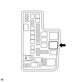
Remove the headlight relay from the engine room relay box LH.
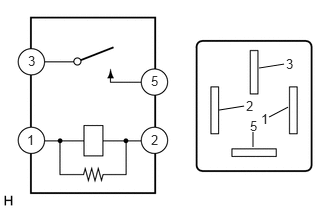
Check the resistance.
Measure the resistance according to the value(s) in the table below.
- Standard Resistance:
Tester Connection Condition Specified Condition 3 - 5 Battery voltage not applied to terminals 1 and 2 10 kΩ or higher Battery voltage applied to terminals 1 and 2 Below 1 Ω
If the result is not as specified, replace the headlight relay.
Install the headlight relay to the engine room relay box LH.
85916D
2.INSPECT FOG LIGHT RELAY (w/ Fog Light)
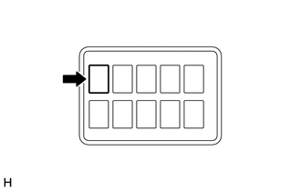
Remove the fog light relay from the engine room relay box RH.
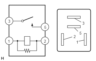
Check the resistance.
Measure the resistance according to the value(s) in the table below.
- Standard Resistance:
Tester Connection Condition Specified Condition 3 - 5 Battery voltage not applied to terminals 1 and 2 10 kΩ or higher Battery voltage applied to terminals 1 and 2 Below 1 Ω
If the result is not as specified, replace the fog light relay.
Install the fog light relay to the engine room relay box RH.
82642A
3.INSPECT RUNNING LIGHT RELAY
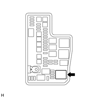
Remove the running light relay from the engine room relay box LH.
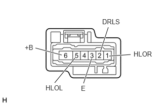
Check the pulses.
Check for pulses according to the value(s) in the table below.
- Standard:
Tester Connection Condition Specified Condition 1 (HLOR) - Negative (-) battery terminal Positive (+) lead of battery connected to terminal 6 (+B) and negative (-) lead connected to terminals 2 (DRLS) and 3 (E) Pulse generation 5 (HLOL) - Negative (-) battery terminal
If the result is not as specified, replace the running light relay.
Install the running light relay to the engine room relay box LH.