SEAT FRONT POWER SEAT CONTROL SYSTEM(w/ Memory) B2650 Slide Sensor Malfunction
DESCRIPTION
When the position control ECU and switch assembly does not receive a sensor signal despite forward or backward movement of the seat by power seat motor operation, this DTC is stored.
| DTC No. | Detection Item | DTC Detection Condition | Trouble Area |
|---|---|---|---|
| B2650 | Slide Sensor Malfunction | The forward and backward lock detection position of the sensor is the same. | ·
Position control ECU and switch assembly ·
Slide motor (Separate type front seat cushion spring assembly) ·
Harness or connector |
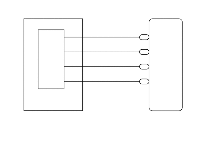
WIRING DIAGRAM
PROCEDURE
Connect the GTS to the DLC3.
Turn the ignition switch to ON.
Turn the GTS on.
Enter the following menus: Body Electrical / Driver Seat / Active Test.
Perform the Active Test according to the display on the GTS.
- Body Electrical > Driver Seat > Active Test
-
Tester Display Measurement Item Control Range Diagnostic Note Seat Slide Operation Seat slide operation OFF/Rear/Front -
- Body Electrical > Driver Seat > Active Test
-
Tester Display Seat Slide Operation - 50004 162 4
- OK:
Motor operates normally.
- Result:
Proceed to OK NG
OK
NG
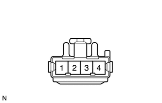
| *a | Front view of wire harness connector
(to Slide Motor [Separate Type Front Seat Cushion Spring Assembly]) |
Disconnect the e12 slide motor connector.
Measure the voltage according to the value(s) in the table below.
- Standard Voltage:
Tester Connection Switch Condition Specified Condition e12-2 - e12-3 Slide switch on 4.8 to 5.1 V
- Result:
Proceed to OK NG
OK
NG
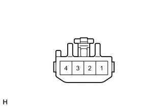
| *a | Component with harness connected
(Slide Motor [Separate Type Front Seat Cushion Spring Assembly]) |
Reconnect the e12 slide motor connector.
Measure the voltage according to the value(s) in the table below.
- Standard Voltage:
Tester Connection Switch Condition Specified Condition e12-2 - Body ground Slide switch on 4.5 to 4.8 V
- Result:
Proceed to OK NG
OK
NG
Disconnect the e6 position control ECU and switch assembly connector.
Measure the resistance according to the value(s) in the table below.
- Standard Resistance:
Tester Connection Condition Specified Condition e6-5 (SSRS) - e12-2 Always Below 1 Ω e6-1 (SGND) - e12-3 Always Below 1 Ω e6-5 (SSRS) - Body ground Always 10 kΩ or higher e6-1 (SGND) - Body ground Always 10 kΩ or higher
- Result:
Proceed to OK NG
OK
NG
Remove the separate type front seat cushion spring assembly.
Click hereVehicle Interior>SEAT>FRONT SEAT ASSEMBLY(for Power Seat)>DISASSEMBLY
Inspect the separate type front seat cushion spring assembly.
Click hereVehicle Interior>SEAT>FRONT SEAT ASSEMBLY(for Power Seat)>INSPECTION
- Result:
Proceed to OK NG
OK
NG
Disconnect the e18 position control ECU and switch assembly connector.
Measure the resistance according to the value(s) in the table below.
- Standard Resistance:
Tester Connection Condition Specified Condition e18-3 (SLD+) - e12-4 Always Below 1 Ω e18-4 (SLD-) - e12-1 Always Below 1 Ω e18-3 (SLD+) - Body ground Always 10 kΩ or higher e18-4 (SLD-) - Body ground Always 10 kΩ or higher
- Result:
Proceed to OK NG
OK
NG