AUDIO / VIDEO INSTRUMENT PANEL SPEAKER INSPECTION
PROCEDURE

 86160P
1.INSPECT FRONT NO. 2 SPEAKER ASSEMBLY
w/o Woofer:
When there is a malfunction such as noise from a speaker or no sound at all, replace the speaker with a new one and check that the malfunction disappears.
- OK:
Malfunction disappears.
- HINT:
- ·
Connect the connectors to the front No. 2 speakers.
·When there is a possibility that either the right or left front No. 2 speaker is defective, inspect by interchanging the right one with the left one.
·Perform the inspection above on both the LH and RH side.
for LH, w/ Woofer:
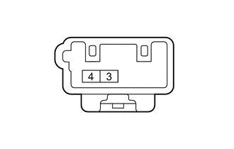
| *a | Component without harness connected
(Front No. 2 Speaker Assembly) |
Measure the resistance according to the value(s) in the table below.
- Standard Resistance:
Tester Connection Condition Specified Condition 3 (TWL-) - 4 (TWL+) Always 3.4 to 5.2 Ω
If the result is not as specified, replace the front No. 2 speaker assembly.
for RH, w/ Woofer:
| *a | Component without harness connected
(Front No. 2 Speaker Assembly) |
Measure the resistance according to the value(s) in the table below.
- Standard Resistance:
Tester Connection Condition Specified Condition 3 (TWR-) - 4 (TWR+) Always 3.4 to 5.2 Ω
If the result is not as specified, replace the front No. 2 speaker assembly.