1AD-FTV STARTING STARTER(w/ Stop And Start System) REASSEMBLY
CAUTION / NOTICE / HINT
PROCEDURE

 28255
1.INSTALL PLANETARY GEAR
Apply high-temperature grease to the planetary gears of the planetary shaft.
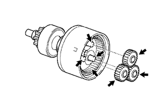

|
High-temperature Grease |
Install the 3 planetary gears.
28177
2.INSTALL STARTER ARMATURE PLATE
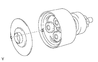
| *a | Protrusion |
| *b | Cutout |
Insert the starter armature plate to the starter center bearing clutch sub-assembly.
Check that the cutout of the starter armature plate fits over the protrusion of the starter center bearing clutch sub-assembly.
28160
3.INSTALL STARTER ARMATURE ASSEMBLY
Install the starter armature assembly to the starter center bearing clutch sub-assembly.
28120
4.INSTALL STARTER YOKE ASSEMBLY
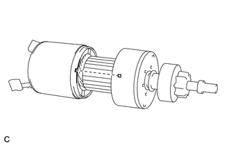
| *a | Cutout |
| *b | Protrusion |
Align the protrusion of the starter center bearing clutch sub-assembly with the cutout of the starter yoke assembly, and install the starter yoke assembly.
28130
5.INSTALL STARTER COMMUTATOR END FRAME ASSEMBLY
Install the starter brush holder assembly.
Using a screwdriver, hold the brush spring back and connect the brush into the starter brush holder assembly.
Connect the 4 brushes.
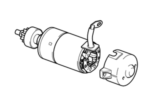
| *a | Groove |
| *b | Rubber |
Align the starter commutator end frame assembly rubber with the groove of the starter yoke assembly.
Install the starter commutator end frame assembly with the 2 screws.
- Torque:
- 3.8 N*m (39 kgf*cm, 34 in.*lbf)
28110
6.INSTALL STARTER DRIVE HOUSING ASSEMBLY
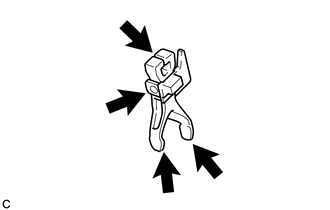
|
|
High-temperature Grease |
Apply high-temperature grease to the starter pinion drive lever.
Install the starter pinion drive lever to the starter center bearing clutch sub-assembly.
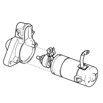
| *a | Protrusion |
| *b | Groove |
Align the protrusion of the starter center bearing clutch sub-assembly with the groove inside the starter drive housing assembly, and install the starter center bearing clutch sub-assembly to the starter drive housing assembly.
Using a T30 "TORX" socket wrench, install the starter drive housing assembly with the 2 through bolts.
- Torque:
- 6.0 N*m (61 kgf*cm, 53 in.*lbf)
28226A
7.INSTALL STARTER MAGNETIC SWITCH ASSEMBLY
Install the starter magnetic switch assembly with the 2 nuts.
- Torque:
- 7.5 N*m (76 kgf*cm, 66 in.*lbf)
Connect the lead wire to the starter magnetic switch assembly with the nut.
- Torque:
- 6.5 N*m (66 kgf*cm, 58 in.*lbf)