AUDIO / VIDEO RADIO RECEIVER REMOVAL
PROCEDURE

 1. PRECAUTION
- NOTICE:
-
After turning the ignition switch off, waiting time may be required before disconnecting the cable from the battery terminal. Therefore, make sure to read the disconnecting the cable from the battery terminal notice before proceeding with work.
-
Click hereGeneral>INTRODUCTION>REPAIR INSTRUCTION>PRECAUTION
2.DISCONNECT CABLE FROM NEGATIVE BATTERY TERMINAL
- NOTICE:
-
When disconnecting the cable, some systems need to be initialized after the cable is reconnected.
-
Click hereGeneral>INTRODUCTION>REPAIR INSTRUCTION>INITIALIZATION
55412C
3.REMOVE CENTER NO. 1 INSTRUMENT CLUSTER FINISH PANEL
55670
4.REMOVE NO. 3 INSTRUMENT PANEL REGISTER ASSEMBLY
55680A
5.REMOVE NO. 4 INSTRUMENT PANEL REGISTER ASSEMBLY
83950M
6.REMOVE TELLTALE LIGHT ASSEMBLY
86120
7.REMOVE RADIO RECEIVER ASSEMBLY (for Radio Receiver Type)
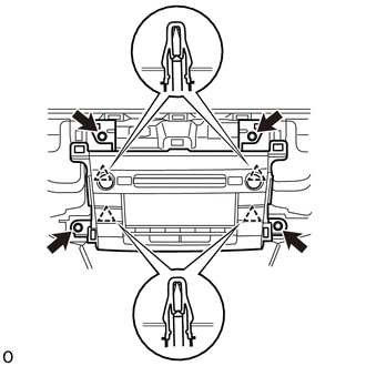
Remove the 4 bolts.
Detach the 4 clips and remove the radio receiver assembly with bracket.
Disconnect each connector.
86140A
8.REMOVE RADIO AND DISPLAY RECEIVER ASSEMBLY (for Radio and Display Type)
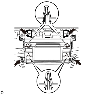
Remove the 4 bolts.
Detach the 4 clips and remove the radio and display receiver assembly with bracket.
Disconnect each connector.
86211
9.REMOVE NO. 1 RADIO BRACKET
Remove the 3 screws and No. 1 radio bracket.
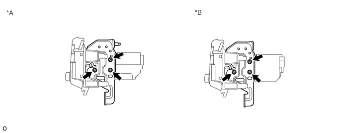
| *A | for Radio Receiver Type | *B | for Radio and Display Type |
86212
10.REMOVE NO. 2 RADIO BRACKET
Remove the 3 screws and No. 2 radio bracket.
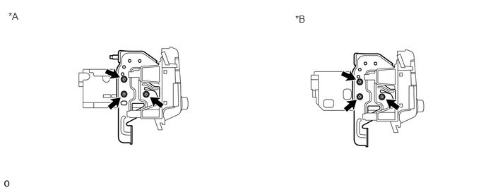
| *A | for Radio Receiver Type | *B | for Radio and Display Type |