EXTERIOR PANELS / TRIM FRONT BUMPER REASSEMBLY
CAUTION / NOTICE / HINT
- HINT:
-
A bolt without a torque specification is shown in the standard bolt chart.
-
Click hereGeneral>SPECIFICATIONS>STANDARD BOLT>SPECIFIED TORQUE FOR STANDARD BOLTS
PROCEDURE

 1.INSTALL FRONT BUMPER MOULDING PROTECTOR (for Type B)
- HINT:
-
When installing the front bumper moulding protector, heat the front bumper moulding using a heat light.
- Standard:
Item Temperature Front Bumper Moulding 20 to 30°C (68 to 86°F)
- NOTICE:
-
Do not heat the front bumper moulding excessively.
Clean the front bumper moulding surface.
Using a heat light, heat the front bumper moulding surface.
Remove the double-sided tape from the front bumper moulding.
Wipe off any tape adhesive residue with cleaner.
Install a new front bumper moulding protector.
Using a brush or felt, apply primer or equivalent to the front bumper moulding protector installation area.
- NOTICE:
- ·
Use a clean brush or felt.
·Do not touch the front bumper assembly until the primer has dried.
Using a heat light, heat the front bumper moulding.
Remove the peeling paper from the face of the front bumper moulding protector.
- HINT:
-
After removing the peeling paper, keep the exposed adhesive free from foreign matter.
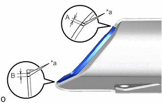
| *a | Mark-off Line |
Install the front bumper moulding protector in the position shown in the illustration.
- HINT:
-
Press the front bumper moulding firmly to install it.
- Standard:
Area Specified Condition A 2.0 mm (0.0787 in.) B 2.0 mm (0.0787 in.)
2.INSTALL FRONT BUMPER MOULDING (for Type B)
- HINT:
-
When installing the front bumper moulding, heat the front bumper moulding sub-assembly and front bumper moulding using a heat light.
- Standard:
Item Temperature Front Bumper Moulding Sub-assembly 20 to 30°C (68 to 86°F) Front Bumper Moulding 20 to 30°C (68 to 86°F)
- NOTICE:
-
Do not heat the front bumper moulding sub-assembly or front bumper moulding excessively.
Clean the front bumper moulding sub-assembly surface.
Using a heat light, heat the front bumper moulding sub-assembly surface.
Remove the double-sided tape from the front bumper moulding sub-assembly.
Wipe off any tape adhesive residue with cleaner.
Install a new front bumper moulding.
Using a brush or felt, apply primer or equivalent to the front bumper moulding installation area.
- NOTICE:
- ·
Use a clean brush or felt.
·Do not touch the front bumper moulding sub-assembly until the primer has dried.
Using a heat light, heat the front bumper moulding sub-assembly and the front bumper moulding.
Temporarily install the front bumper moulding to the front bumper moulding sub-assembly.
Remove the peeling paper from the face of the front bumper moulding.
- HINT:
-
After removing the peeling paper, keep the exposed adhesive free from foreign matter.
Install the front bumper moulding.
- HINT:
-
Press the front bumper moulding firmly to install it.
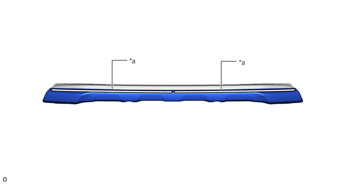
| *a | Double-sided Tape | - | - |
52711
3.INSTALL FRONT BUMPER MOULDING SUB-ASSEMBLY
Install the front bumper moulding with the 9 retainers.
52411
4.INSTALL FRONT BUMPER GUARD
Install the front bumper guard with the 8 retainers.
53128A
5.INSTALL LOWER RADIATOR GRILLE LH
Attach the 4 claws to install the lower radiator grille LH.
Install the 2 clips.
53127A
6.INSTALL LOWER RADIATOR GRILLE RH
- HINT:
-
Use the same procedure described for the LH side.
53128A
7.INSTALL LOWER RADIATOR GRILLE LH (for Automatic Transaxle (U660F))
Attach the 4 claws to install the lower radiator grille LH.
Install the 2 clips.
53112E
8.INSTALL LOWER NO. 1 RADIATOR GRILLE
Attach the 18 claws to install the lower No. 1 radiator grille.
52113D
9.INSTALL FRONT BUMPER EXTENSION LH
Install the front bumper extension LH with the 5 retainers.
52112D
10.INSTALL FRONT BUMPER EXTENSION RH
- HINT:
-
Use the same procedure described for the LH side.
53286C
11.INSTALL FRONT BUMPER ARM HOLE COVER LH
Attach the 2 claws to install the front bumper arm hole cover LH.
53285J
12.INSTALL FRONT BUMPER ARM HOLE COVER RH
- HINT:
-
Use the same procedure described for the LH side.
75301A
13.INSTALL FRONT BUMPER EMBLEM SUB-ASSEMBLY
Attach the 2 claws to install the front bumper emblem sub-assembly.
53106C
14.INSTALL RADIATOR GRILLE GARNISH SUB-ASSEMBLY LH
Attach the 4 clips to install the radiator garnish sub-assembly LH.
Attach the claw.
Install the 2 screws.
53105A
15.INSTALL RADIATOR GRILLE GARNISH SUB-ASSEMBLY RH
- HINT:
-
Use the same procedure described for the LH side.
52128C
16.INSTALL FRONT BUMPER HOLE COVER LH (w/o Fog Light)
Install the front bumper hole cover LH with the 2 screws.
Install the clip.
52127D
17.INSTALL FRONT BUMPER HOLE COVER RH (w/o Fog Light)
- HINT:
-
Use the same procedure described for the LH side.
52128C
18.INSTALL FRONT BUMPER HOLE COVER LH (w/ Fog Light)
Install the front bumper hole cover LH with the 2 screws.
Install the clip.
52127D
19.INSTALL FRONT BUMPER HOLE COVER RH (w/ Fog Light)
- HINT:
-
Use the same procedure described for the LH side.
81220
20.INSTALL FOG LIGHT ASSEMBLY LH (w/ Fog Light)
81210A
21.INSTALL FOG LIGHT ASSEMBLY RH (w/ Fog Light)
- HINT:
-
Use the same procedure described for the LH side.
53395E
22.INSTALL HOOD TO FRONT END PANEL SEAL
- HINT:
-
When installing the hood to front end panel seal, heat the front bumper cover using a heat light.
- Standard:
Item Temperature Front Bumper Cover 20 to 30°C (68 to 86°F)
- NOTICE:
-
Do not heat the front bumper cover excessively.
Clean the front bumper cover surface.
Using a heat light, heat the front bumper cover surface.
Remove the double-sided tape from the front bumper cover.
Wipe off any tape adhesive residue with cleaner.
When reusing the front bumper cover:
Using a heat light, heat the front bumper cover surface.
Remove the double-sided tape from the front bumper cover.
Wipe off any tape adhesive residue with cleaner.
Install a new hood to front end panel seal.
Using a heat light, heat the front bumper cover.
Remove the peeling paper from the face of the hood to front end panel seal.
- HINT:
-
After removing the peeling paper, keep the exposed adhesive free from foreign matter.
Attach the 9 clips to install the hood to front end panel seal.
- HINT:
-
Press the hood to front end panel seal firmly to install it.
85208A
23.INSTALL HEADLIGHT WASHER ACTUATOR SUB-ASSEMBLY LH (w/ Headlight Cleaner System)
85207A
24.INSTALL HEADLIGHT WASHER ACTUATOR SUB-ASSEMBLY RH (w/ Headlight Cleaner System)
- HINT:
-
Use the same procedure described for the LH side.
25.INSTALL HEADLIGHT CLEANER HOSE (w/ Headlight Cleaner System)
85045
26.INSTALL TYPE 1 HEADLIGHT WASHER NOZZLE SUB-ASSEMBLY LH (w/ Headlight Cleaner System)
85044
27.INSTALL TYPE 1 HEADLIGHT WASHER NOZZLE SUB-ASSEMBLY RH (w/ Headlight Cleaner System)
- HINT:
-
Use the same procedure described for the LH side.