EA64 MANUAL TRANSMISSION / TRANSAXLE SHIFT AND SELECT LEVER SHAFT REASSEMBLY
PROCEDURE

 33528C
1.INSTALL CONTROL SHAFT COVER OIL SEAL
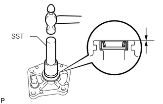
Using SST and a hammer, install a new control shaft cover oil seal to the control shaft cover.
- SST
- 09307-12010
- Standard depth:
0 to 0.5 mm (0 to 0.0196 in.)
Coat the lip of the control shaft cover oil seal with MP grease.
33544C
2.INSTALL SHIFT LEVER DAMPER
Clean the threads of the bolt and shift lever damper hole.
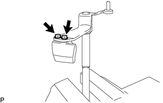
Apply a few drops of adhesive to 2 or 3 threads of the 2 bolts.
- Adhesive:
Toyota Genuine Adhesive 1344, Three Bond 1344 or equivalent
Install the shift lever damper to the shift and select lever shaft with the 2 bolts.
- Torque:
- 18.6 N*m (190 kgf*cm, 14 ft.*lbf)
33111J
3.INSTALL PIN
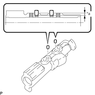
| *a | Standard depth |
Install the 2 pins to the inner No. 1 shift lever.
- Standard depth:
3.5 to 4.5 mm (0.138 to 0.177 in.)
33266C
4.INSTALL SHIFT GATE PLATE
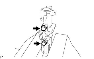
Install the shift gate plate with the 2 bolts.
- Torque:
- 8.5 N*m (87 kgf*cm, 75 in.*lbf)
33261C
5.INSTALL SHIFT AND SELECT LEVER SHAFT
Coat the shift and select lever boot lip with MP grease.
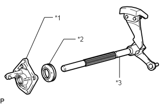
| *1 | Control Shaft Cover |
| *2 | Shift and Select Lever Boot |
| *3 | Shift and Select Lever Shaft |
Install the shift and select lever boot and control shaft cover to the select lever shaft.
33251A
6.INSTALL INNER NO. 1 SHIFT LEVER
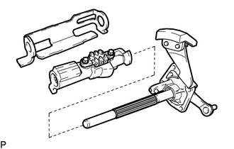
Install the inner No. 1 shift lever and shift interlock plate to the shift and select lever shaft.
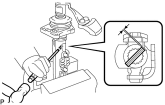
Using a 5 mm pin punch and hammer, tap a new slotted spring pin into the inner No. 1 shift lever.
- Standard depth:
0.4 to 1.4 mm (0.0158 to 0.0551 in.)