RM3090E
_56
Audio / Visual / Telematics
_008776
NAVIGATION / MULTI INFO DISPLAY
_0148247
NAVIGATION SYSTEM(for Radio and Display Type)
J
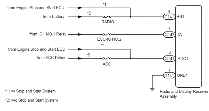
NAVIGATION / MULTI INFO DISPLAY NAVIGATION SYSTEM(for Radio and Display Type) Radio Receiver Power Source Circuit
DESCRIPTION
This circuit provides power to the radio and display receiver assembly.
WIRING DIAGRAM
0.25,0.177 4.833,0.375
4.583,0.198
10
false
from Engine Stop and Start ECU
1.469,0.479 4.917,0.667
3.448,0.188
10
false
from Battery
1.01,1.083 4.844,1.271
3.833,0.188
10
false
from IG1 NO.1 Relay
0.281,1.604 4.646,1.792
4.365,0.188
10
false
from Engine Stop and Start ECU
1.26,1.896 4.719,2.083
3.458,0.188
10
false
from ACC Relay
3.479,0.667 6.792,0.854
3.313,0.188
10
false
RADIO
3.333,1.26 6.646,1.448
3.313,0.188
10
false
ECU-IG NO.2
3.521,2.115 6.615,2.313
3.094,0.198
10
false
ACC
2.958,1.802 3.177,1.979
0.219,0.177
10
false
*2
3.469,1.479 3.688,1.656
0.219,0.177
10
false
*1
3.521,0.063 3.74,0.24
0.219,0.177
10
false
*1
2.99,0.365 3.208,0.542
0.219,0.177
10
false
*2
5.76,0.302 5.979,0.479
0.219,0.177
10
false
4
5.76,0.896 5.979,1.073
0.219,0.177
10
false
1
5.781,1.708 6,1.885
0.219,0.177
10
false
3
5.781,2.292 6,2.469
0.219,0.177
10
false
7
5.635,0.49 6.438,0.698
0.802,0.208
10
false
G141
5.646,1.104 6.448,1.313
0.802,0.208
10
false
G143
5.646,1.927 6.448,2.135
0.802,0.208
10
false
G141
5.635,2.51 6.438,2.719
0.802,0.208
10
false
G141
6.073,0.479 6.875,0.688
0.802,0.208
10
false
+B1
6.094,1.115 6.896,1.323
0.802,0.208
10
false
IG
6.094,1.927 6.896,2.135
0.802,0.208
10
false
ACC1
6.063,2.5 6.865,2.708
0.802,0.208
10
false
GND1
5.479,3.052 7.156,3.417
1.677,0.365
10
false
Radio and Display Receiver Assembly
0.177,3.042 3.49,3.219
3.313,0.177
10
false
*1: w/ Stop and Start System
0.177,3.354 3.49,3.531
3.313,0.177
10
false
*2: w/o Stop and Start System
CAUTION / NOTICE / HINT
- NOTICE:
- ·
Inspect the fuses for circuits related to this system before performing the following inspection procedure.
·Check that the wire harness is properly installed and does not have any sharp bends, pinching or loose connections.
Click hereGeneral>INTRODUCTION>HOW TO TROUBLESHOOT ECU CONTROLLED SYSTEMS>HOW TO PROCEED WITH TROUBLESHOOTING
PROCEDURE
1.CHECK HARNESS AND CONNECTOR (RADIO AND DISPLAY RECEIVER ASSEMBLY - BATTERY AND BODY GROUND)
a.
0.458,0.833 0.896,1.052
0.438,0.219
0.375,2.448 0.813,2.667
0.438,0.219
0.688,2.917 0.844,2.917
0.844,2.917 1.083,2.563
true
1.208,1.417 1.365,1.417
1.365,1.417 1.604,1.063
true
2.406,0.375 2.229,0.375
2.229,0.375 1.927,0.75
true
2.521,1.021 2.333,1.021
2.333,1.021 2.135,0.865
true
0.052,0.042 0.365,0.198
0.313,0.156
10
false
*a
0.5,0.875 0.854,1.083
0.354,0.208
10
false
G141
0.427,2.49 0.969,2.688
0.542,0.198
10
false
G143
0.802,1.333 1.323,1.542
0.521,0.208
10
false
GND1
2.458,0.313 3.021,0.531
0.563,0.219
10
false
ACC1
2.563,0.948 3.125,1.167
0.563,0.219
10
false
+B1
0.51,2.833 0.865,3.042
0.354,0.208
10
false
IG
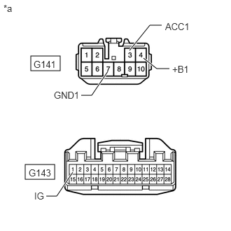
| *a | Front view of wire harness connector
(to Radio and Display Receiver Assembly) |
Disconnect the radio and display receiver assembly connectors.
b.
Measure the resistance according to the value(s) in the table below.
- Standard Resistance:
Tester Connection Condition Specified Condition G141-7 (GND1) - Body ground Always Below 1 Ω
c.
Measure the voltage according to the value(s) in the table below.
- Standard Voltage:
Tester Connection Condition Specified Condition G141-4 (+B1) - Body ground*1 Always 9.5 to 14 V G141-4 (+B1) - Body ground*2 Always 11 to 14 V G141-3 (ACC1) - Body ground*1 Ignition switch ACC 9.5 to 14 V G141-3 (ACC1) - Body ground*2 Ignition switch ACC 11 to 14 V G143-1 (IG) - Body ground Ignition switch ON 11 to 14 V
*1: w/ Stop and Start System
*2: w/o Stop and Start System
- Result:
Proceed to OK NG
OK
PROCEED TO NEXT SUSPECTED AREA SHOWN IN PROBLEM SYMPTOMS TABLE
NG
REPAIR OR REPLACE HARNESS OR CONNECTOR