Home › Audio / Visual / Telematics › NAVIGATION / MULTI INFO DISPLAY › NAVIGATION SYSTEM(for Radio and Display Type) › from 2015.10
RM3090E _56 Audio / Visual / Telematics _008776 NAVIGATION / MULTI INFO DISPLAY _0148247 NAVIGATION SYSTEM(for Radio and Display Type) C

NAVIGATION / MULTI INFO DISPLAY  NAVIGATION SYSTEM(for Radio and Display Type)  B15D8  Monitor Disconnected  


DESCRIPTION

The parking assist ECU and radio and display receiver assembly are connected by an AVC-LAN communication line. When an AVC-LAN communication error occurs between the radio and display receiver assembly and parking assist ECU, these DTCs will be stored.

DTC No. Detection Item DTC Detection Condition Trouble Area
B15D8 Monitor Disconnected A device that is listed in the AVC-LAN connected device record of the master unit is missing.
·

AVC-LAN circuit

·

Parking assist ECU

·

Radio and display receiver assembly


HINT:
·

Even if no fault is present, this DTC may be stored depending on the battery condition.

·

The radio and display receiver assembly is the master unit.


WIRING DIAGRAM
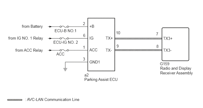
E330588E02
1.927,1 3.458,1.198 1.531,0.198 10 false ECU-B NO.1 1.885,1.406 3.417,1.604 1.531,0.198 10 false ECU-IG NO. 2 1.99,1.823 3.521,2.021 1.531,0.198 10 false ACC 0.771,0.844 2.302,1.042 1.531,0.198 10 false from Battery 0.292,1.26 1.823,1.458 1.531,0.198 10 false from IG NO. 1 Relay 0.542,1.688 2.073,1.885 1.531,0.198 10 false from ACC Relay 3.156,0.844 7.156,1.031 4,0.188 10 false +B 3.156,1.26 7.156,1.448 4,0.188 10 false IG 3.156,1.677 7.156,1.865 4,0.188 10 false ACC 3.156,2.104 7.156,2.292 4,0.188 10 false GND1 3.729,1.26 5.313,1.49 1.583,0.229 10 false TX+ 3.729,1.688 7.156,1.865 3.427,0.177 10 false TX- 4.115,1.542 4.427,1.74 0.313,0.198 10 false 9 4.094,1.073 4.406,1.271 0.313,0.198 10 false 10 5.51,1.115 5.823,1.313 0.313,0.198 10 false 7 5.521,1.552 5.833,1.75 0.313,0.198 10 false 8 5.76,1.688 7.156,1.906 1.396,0.219 10 false TX3- 5.76,1.271 7.156,1.49 1.396,0.219 10 false TX3+ 2.979,2.719 4.51,2.917 1.531,0.198 10 false Parking Assist ECU 2.979,2.563 3.906,2.719 0.927,0.156 10 false a2 5.646,2.167 6.594,2.365 0.948,0.198 10 false G159 5.656,2.323 6.854,2.656 1.198,0.333 10 false Radio and Display Receiver Assembly 0.885,3.427 3.635,3.646 2.75,0.219 10 false : AVC-LAN Communication Line 2.927,0.75 3.24,0.948 0.313,0.198 10 false 2 2.938,1.167 3.115,1.354 0.177,0.188 10 false 6 2.927,1.583 3.24,1.781 0.313,0.198 10 false 1 2.927,2 3.24,2.198 0.313,0.198 10 false 3

CAUTION / NOTICE / HINT

NOTICE:
·

Inspect the fuses for circuits related to this system before performing the following inspection procedure.

·

Check that the wire harness is properly installed and does not have any sharp bends, pinching or loose connections

Click hereGeneral>INTRODUCTION>HOW TO TROUBLESHOOT ECU CONTROLLED SYSTEMS>HOW TO PROCEED WITH TROUBLESHOOTING


PROCEDURE

1.CLEAR DTC
a.

Clear the DTCs.

Click hereAudio / Visual / Telematics>NAVIGATION / MULTI INFO DISPLAY>NAVIGATION SYSTEM(for Radio and Display Type)>DTC CHECK / CLEAR

Body Electrical > Navigation System > Clear DTCs
50002 212

Result:
Proceed to
NEXT


NEXT

2.CHECK FOR DTC
2.CHECK FOR DTC
a.

Recheck for DTCs and check if the same DTC is output again.

Click hereAudio / Visual / Telematics>NAVIGATION / MULTI INFO DISPLAY>NAVIGATION SYSTEM(for Radio and Display Type)>DTC CHECK / CLEAR

Body Electrical > Navigation System > Trouble Codes
50001 212
OK:

No DTCs are output.


Result:
Proceed to
OK
NG


OK

NG

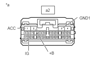
3.CHECK HARNESS AND CONNECTOR (PARKING ASSIST ECU - BATTERY AND BODY GROUND)
a.
E297790E01
1.438,0.208 1.896,0.49 0.458,0.281 2.177,0.969 2.688,0.604 true 1.667,1.792 1.219,1.021 true 0.885,0.979 0.604,0.979 true 1,1.167 0.99,1.76 true 0.198,0.083 0.51,0.24 0.313,0.156 10 false *a 0.26,0.896 0.573,1.052 0.313,0.156 10 false ACC 1.708,1.76 2.021,1.917 0.313,0.156 10 false +B 2.76,0.542 3.26,0.708 0.5,0.167 10 false GND1 0.865,1.771 1.365,1.938 0.5,0.167 10 false IG 1.583,0.271 1.896,0.469 0.313,0.198 10 false a2

Disconnect the parking assist ECU connector.


b.

Measure the resistance according to the value(s) in the table below.

Standard Resistance:
Tester Connection Condition Specified Condition
a2-3 (GND1) - Body ground Always Below 1 Ω


c.

Measure the voltage according to the value(s) in the table below.

Standard Voltage:
Tester Connection Condition Specified Condition
a2-2 (+B) - a2-3 (GND1) Always 11 to 14 V
a2-6 (IG) - a2-3 (GND1) Ignition switch ON 11 to 14 V
a2-1 (ACC) - a2-3 (GND1) Ignition switch ACC 11 to 14 V


Result:
Proceed to
OK
NG


OK

4.INSPECT RADIO & DISPLAY RECEIVER ASSEMBLY

NG

REPAIR OR REPLACE HARNESS OR CONNECTOR

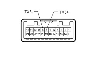
4.INSPECT RADIO & DISPLAY RECEIVER ASSEMBLY
a.
E333570E01
1.656,1.01 1.906,0.417 1.906,0.417 2.052,0.417 false 1.521,1.01 1.333,0.406 1.333,0.406 1.208,0.406 false 0.865,0.333 1.229,0.521 0.365,0.188 10 false TX3- 2.104,0.344 2.448,0.51 0.344,0.167 10 false TX3+

Remove the radio and display receiver assembly.

Click hereAudio / Visual / Telematics>AUDIO / VIDEO>RADIO RECEIVER>REMOVAL


b.

Measure the resistance according to the value(s) in the table below.

Standard Resistance:
Tester Connection Condition Specified Condition
7 (TX3+) - 8 (TX3-) Always 60 to 80 Ω


Result:
Proceed to
OK
NG


OK

5.CHECK HARNESS AND CONNECTOR (RADIO AND DISPLAY RECEIVER ASSEMBLY - PARKING ASSIST ECU)

NG

REPLACE RADIO & DISPLAY RECEIVER ASSEMBLY

5.CHECK HARNESS AND CONNECTOR (RADIO AND DISPLAY RECEIVER ASSEMBLY - PARKING ASSIST ECU)
a.

Disconnect the G159 radio and display receiver assembly connector.


b.

Disconnect the a2 parking assist ECU connector.


c.

Measure the resistance according to the value(s) in the table below.

Standard Resistance:
Tester Connection Condition Specified Condition
G159-7 (TX3+) - a2-10 (TX+) Always Below 1 Ω
G159-8 (TX3-) - a2-9 (TX-) Always Below 1 Ω
G159-7 (TX3+) - Body ground Always 10 kΩ or higher
G159-8 (TX3-) - Body ground Always 10 kΩ or higher


Result:
Proceed to
OK
NG


OK

6.REPLACE PARKING ASSIST ECU

NG

REPAIR OR REPLACE HARNESS OR CONNECTOR

6.REPLACE PARKING ASSIST ECU
a.

Replace the parking assist ECU with a new or normally functioning one.

Click hereAudio / Visual / Telematics>PARK ASSIST / MONITORING>PARKING ASSIST ECU>REMOVAL


Result:
Proceed to
NEXT


NEXT

7.CLEAR DTC
7.CLEAR DTC
a.

Clear the DTCs.

Click hereAudio / Visual / Telematics>NAVIGATION / MULTI INFO DISPLAY>NAVIGATION SYSTEM(for Radio and Display Type)>DTC CHECK / CLEAR

Body Electrical > Navigation System > Clear DTCs
50002 212

Result:
Proceed to
NEXT


NEXT

8.CHECK FOR DTC
8.CHECK FOR DTC
a.

Recheck for DTCs and check if the same DTC is output again.

Click hereAudio / Visual / Telematics>NAVIGATION / MULTI INFO DISPLAY>NAVIGATION SYSTEM(for Radio and Display Type)>DTC CHECK / CLEAR

Body Electrical > Navigation System > Trouble Codes
50001 212
OK:

No DTCs are output.


Result:
Proceed to
OK
NG


OK

END (PARKING ASSIST ECU IS DEFECTIVE)

NG

REPLACE RADIO & DISPLAY RECEIVER ASSEMBLY