RM3090E
_52
Drivetrain
_008436
U660F AUTOMATIC TRANSMISSION / TRANSAXLE
_0047080
AUTOMATIC TRANSAXLE SYSTEM
U
U660F AUTOMATIC TRANSMISSION / TRANSAXLE AUTOMATIC TRANSAXLE SYSTEM TERMINALS OF ECU
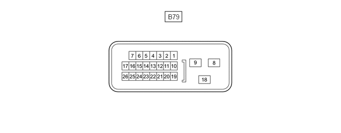
TCM
3.469,0.24 3.823,0.458
0.354,0.219
3.531,0.271 3.906,0.5
0.375,0.229
10
B79
- HINT:
-
The standard voltage at each TCM terminal is shown in the table below.
-
In the table, first follow the information under "Condition". Look under "Terminal No. (Symbol)" for the terminals to inspect. The standard voltage between the terminals is shown under "Specified Condition".
-
Use the illustration above as a reference for the TCM terminals.
| Terminal No. (Symbol) | Wiring Color | Terminal Description | Condition | Specified Condition |
|---|---|---|---|---|
| B79-15 (R) - B79-8 (E1) | R - BR | R position switch signal | Ignition switch ON and shift lever in R | 11 to 14 V |
| Ignition switch ON and shift lever in any position except R | Below 1 V | |||
| B79-16 (D) - B79-8 (E1) | B - BR | D position switch signal | Ignition switch ON and shift lever in D or M | 11 to 14 V |
| Ignition switch ON and shift lever in any position except D or M | Below 1 V | |||
| B79-12 (STP) - B79-8 (E1) | L - BR | Stop light switch signal | Brake pedal depressed | 7.5 to 14 V |
| Brake pedal released | Below 1.5 V | |||
| B79-11 (NSW) - B79-8 (E1) | W - BR | Park/neutral position switch signal | Ignition switch ON and shift lever in P or N | Below 2 V |
| Ignition switch ON and shift lever in any position except P or N | 11 to 14 V | |||
| B79-10 (STA) - B79-8 (E1) | LG - BR | Starter signal | Cranking (shift lever in P or N) | 6 V or higher |
| Ignition switch ON and shift lever in P or N | Below 2 V | |||
| B79-3 (SPD) - B79-8 (E1) | V - BR | Speed signal from combination meter | Vehicle driving | Pulse generation |
| B79-1 (BATT) - B79-8 (E1) | W - BR | Battery (for measuring battery voltage and for TCM memory) | Always | 11 to 14 V |
| B79-13 (IGSW) - B79-8 (E1) | Y - BR | Ignition switch | Ignition switch ON | 11 to 14 V |
| B79-18 (+B) - B79-8 (E1) | B - BR | Power source of TCM | Ignition switch ON | 11 to 14 V |
| B79-6 (CAN+) - B79-8 (E1) | Y - BR | CAN communication line | Ignition switch ON | Pulse generation |
| B79-7 (CAN-) - B79-8 (E1) | B - BR | CAN communication line | Ignition switch ON | Pulse generation |
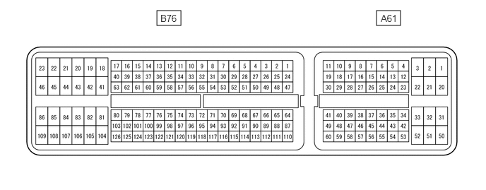
ECM
2.313,0.156 2.667,0.375
0.354,0.219
5.552,0.156 5.906,0.375
0.354,0.219
2.365,0.188 2.74,0.417
0.375,0.229
10
B76
5.615,0.188 5.99,0.417
0.375,0.229
10
A61
- HINT:
-
The standard voltage at each ECM terminal is shown in the table below.
-
In the table, first follow the information under "Condition". Look under "Terminal No. (Symbol)" for the terminals to inspect. The standard voltage between the terminals is shown under "Specified Condition".
-
Use the illustration below as a reference for the ECM terminals.
| Terminal No. (Symbol) | Wiring Color | Terminal Description | Condition | Specified Condition |
|---|---|---|---|---|
| A61-9 (S) - B76-109 (E1) | L - BR | M position switch signal | Ignition switch ON and shift lever in M | 11 to 14 V |
| Ignition switch ON and shift lever not in M | Below 1 V | |||
| B76-61 (SFTU) - B76-109 (E1) | LG - BR | Up-shift position switch signal | Ignition switch ON and shift lever in M | 11 to 14 V |
| Ignition switch ON and shift lever in "+" (up-shift) | Below 1 V | |||
| A61-28 (SFTD) - B76-109 (E1) | Y - BR | Down-shift position switch signal | Ignition switch ON and shift lever in M | 11 to 14 V |
| Ignition switch ON and shift lever in "-" (down-shift) | Below 1 V | |||
| A61-36 (PWMS) - B76-109 (E1) | GR - BR | Combination switch (SPORT) signal | Ignition switch ON and combination switch (SPORT) off | 11 to 14 V |
| Ignition switch ON and combination switch (SPORT) on | Below 1.5 V |