EXTERIOR PANELS / TRIM REAR BUMPER REMOVAL
PROCEDURE

 1. PRECAUTION (w/ Touchless Power Back Door)
- NOTICE:
-
After turning the ignition switch off, waiting time may be required before disconnecting the cable from the battery terminal. Therefore, make sure to read the disconnecting the cable from the battery terminal notice before proceeding with work.
-
Click hereGeneral>INTRODUCTION>REPAIR INSTRUCTION>PRECAUTION
2.DISCONNECT CABLE FROM NEGATIVE BATTERY TERMINAL (w/ Touchless Power Back Door)
- CAUTION:
-
Wait at least 90 seconds after disconnecting the cable from the negative (-) battery terminal to disable the SRS system.
- NOTICE:
-
When disconnecting the cable, some systems need to be initialized after the cable is reconnected.
-
Click hereGeneral>INTRODUCTION>REPAIR INSTRUCTION>INITIALIZATION
76626E
3.REMOVE REAR QUARTER PANEL MUDGUARD LH (w/ Mudguard)
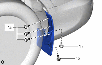
| *a | Screw A |
| *b | Screw B |
Remove the 2 screws labeled B.
Remove the 3 screws labeled A and rear quarter panel mudguard LH.
76625G
4.REMOVE REAR QUARTER PANEL MUDGUARD RH (w/ Mudguard)
- HINT:
-
Use the same procedure described for the LH side.
52159
5.REMOVE REAR BUMPER COVER
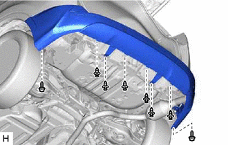
Remove the 6 clips.
Remove the 2 screws.
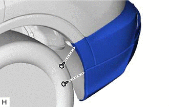
w/o Mudguard
Remove the 2 screws.
- HINT:
-
Use the same procedure for the other side.
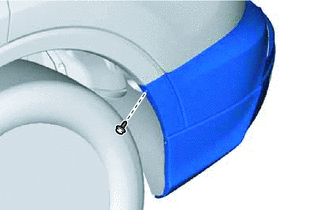
w/ Mudguard
Remove the screws.
- HINT:
-
Use the same procedure for the other side.
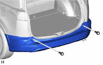
Remove the 2 bolts.
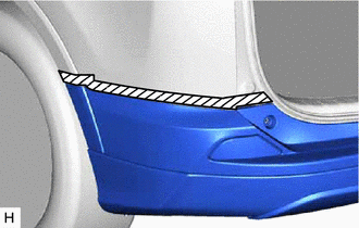

|
Protective Tape |
Put protective tape around the rear bumper cover.
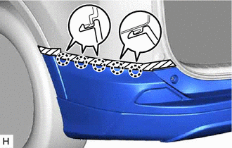
Detach the 5 claws.
- HINT:
-
Use the same procedure to detach the claw on the other side.
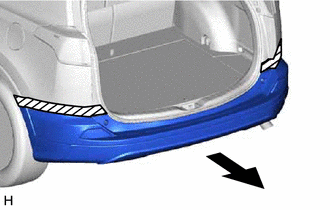
Remove the rear bumper cover as shown in the illustration.
Disconnect each connector.
58724
6.REMOVE NO. 2 LUGGAGE COMPARTMENT SERVICE COVER PROTECTOR
Remove the 2 clips and No. 2 luggage compartment service cover protector.
58723
7.REMOVE NO. 1 LUGGAGE COMPARTMENT SERVICE COVER PROTECTOR
- HINT:
-
Use the same procedure described for the LH side.
52023
8.REMOVE REAR BUMPER REINFORCEMENT SUB-ASSEMBLY
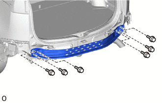
for Step Type:
Remove the 6 bolts and rear bumper reinforcement sub-assembly.
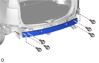
w/ TOYOTA Parking Assist-sensor System:
Remove the 6 bolts and rear bumper reinforcement sub-assembly.
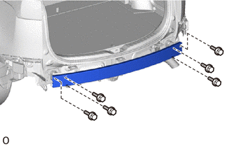
for Standard Type:
Remove the 6 bolts and rear bumper reinforcement sub-assembly.
52016A
9.REMOVE REAR BUMPER ARM SUB-ASSEMBLY LH
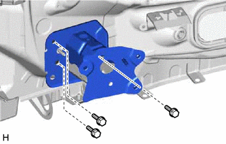
Remove the 3 bolts and rear bumper arm sub-assembly LH.
52015A
10.REMOVE REAR BUMPER ARM SUB-ASSEMBLY RH
- HINT:
-
Use the same procedure described for the LH side.
52156A
11.REMOVE REAR BUMPER SIDE SUPPORT LH
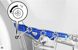
| *a | 90° |
Using a screwdriver, turn the clip 90° and remove the clip.
Remove the screw.
Detach the 3 claws and rear bumper side support LH.
52155A
12.REMOVE REAR BUMPER SIDE SUPPORT RH
- HINT:
-
Use the same procedure described for the LH side.
52563A
13.REMOVE REAR BUMPER UPPER RETAINER LH
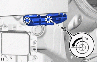
| *a | 90° |
Using a screwdriver, turn the clip 90° and remove the clip.
Detach the 2 claws and rear bumper upper retainer LH.
52562B
14.REMOVE REAR BUMPER UPPER RETAINER RH
- HINT:
-
Use the same procedure described for the LH side.