BODY PANEL FRONT SIDE MEMBER ASSEMBLY REPLACEMENT
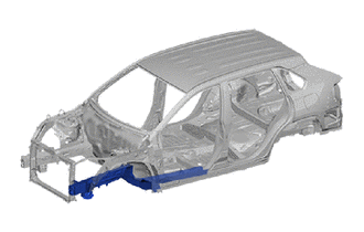
With the front fender apron assembly removed.
REMOVAL
| Symbol Meaning | |
|---|---|

|
Remove Weld Points |
Do not butt weld or heat repair because the heat decreases the strength of areas where ultra high strength steel is used. (See the introduction)
Remove the torque box sub-assembly front and front side member reinforce sub-assembly No.2.
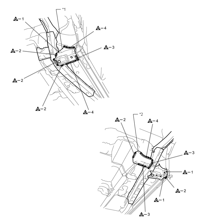
| *1 | TORQUE BOX SUB-ASSEMBLY FRONT | *2 | FRONT SIDE MEMBER REINFORCE SUB-ASSEMBLY NO.2 |
Remove the front side member inner rear.
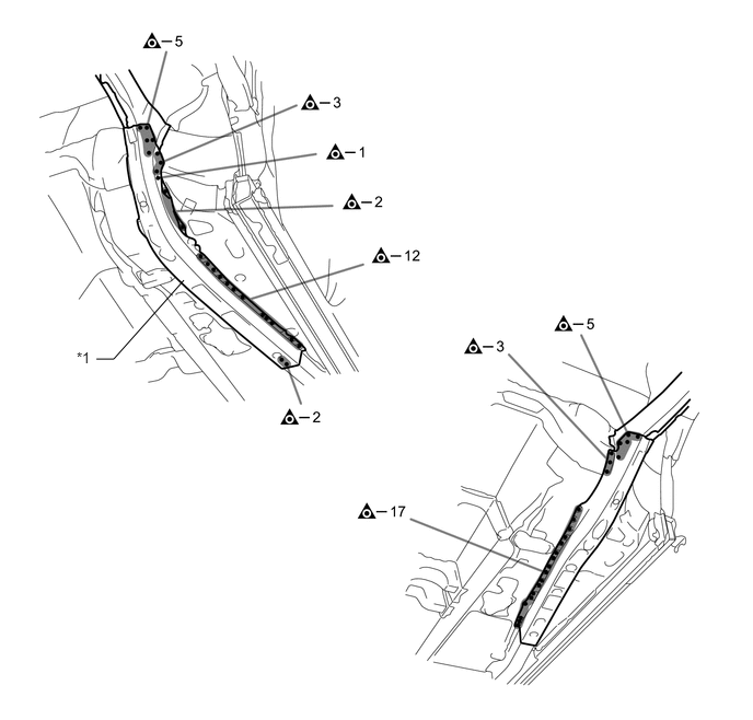
| *1 | FRONT SIDE MEMBER INNER REAR | - | - |
Remove the front side member sub-assembly outer and converter support bracket sub-assembly or front side member sub-assembly inner.
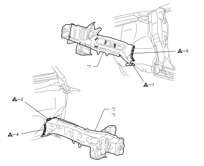
| *1 | FRONT SIDE MEMBER SUB-ASSEMBLY OUTER | *2 | CONVERTER SUPPORT BRACKET SUB-ASSEMBLY (LH) |
| *3 | FRONT SIDE MEMBER SUB-ASSEMBLY INNER (RH) | - | - |
INSTALLATION
| Symbol Meaning | |
|---|---|

|
Plug Weld |

|
Fillet Weld |
Temporarily install the new parts and measure each part of the new parts in accordance with the body dimension diagram. (See the body dimensions)
Make sure to attach correctly in accordance with the body dimension diagram as this part affects the front wheel alignment.
Before temporarily installing the new parts, weld the front side member inner rear, front side member reinforcement front and engine rear mounting member bracket with the standard number of welding points.
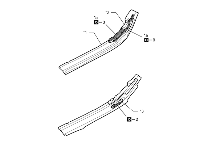
| *1 | FRONT SIDE MEMBER INNER REAR | *2 | FRONT SIDE MEMBER REINFORCEMENT FRONT |
| *3 | ENGINE REAR MOUNTING MEMBER BRACKET | - | - |
| *a | Ultra High Strength Steel Welding Point | - | - |
When welding 2 panels together including 780 MPa ultra high strength steel.
| *a: Plug weld | Plug diameter | 10 mm (0.39 in.) |
| Wire type | AWS A5.18 ER70S-3 | |
| Shield gas | Metal active gas |
- NOTICE:
-
Be sure to use Metal active gas (Ar 80% + CO2 20%) as the shield gas when plug welding.Sufficient weld strength cannot be assured when using 100% CO2 shield gas.
Weld the front side member sub-assembly outer and converter support bracket sub-assembly or front side member sub-assembly inner to the vehicle side.
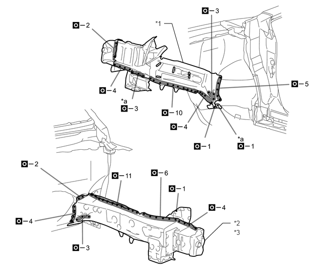
| *1 | FRONT SIDE MEMBER SUB-ASSEMBLY OUTER | *2 | CONVERTER SUPPORT BRACKET SUB-ASSEMBLY (LH) |
| *3 | FRONT SIDE MEMBER SUB-ASSEMBLY INNER (RH) | - | - |
| *a | Ultra High Strength Steel Welding Point | - | - |
When welding 2 panels together including 980 MPa ultra high strength steel.
| *a: Plug weld | Plug diameter | 10 mm (0.39 in.) |
| Wire type | AWS A5.18 ER70S-3 | |
| Shield gas | Metal active gas |
- NOTICE:
-
Be sure to use Metal active gas (Ar 80% + CO2 20%) as the shield gas when plug welding.Sufficient weld strength cannot be assured when using 100% CO2 shield gas.
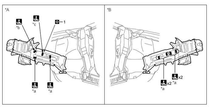
| *A | LH | *B | RH |
| *a | 25 mm (0.98 in.) | *b | 32 mm (1.26 in.) |
| *c | 29 mm (1.14 in.) | - | - |
Weld the front side member inner rear to the vehicle side.
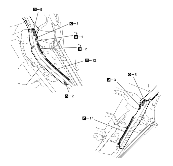
| *1 | FRONT SIDE MEMBER INNER REAR | - | - |
| *a | Ultra High Strength Steel Welding Point | - | - |
When welding 2 panels together including 780 MPa ultra high strength steel.
| *a: Plug weld | Plug diameter | 10 mm (0.39 in.) |
| Wire type | AWS A5.18 ER70S-3 | |
| Shield gas | Metal active gas |
- NOTICE:
-
Be sure to use Metal active gas (Ar 80% + CO2 20%) as the shield gas when plug welding.Sufficient weld strength cannot be assured when using 100% CO2 shield gas.
Weld the torque box sub-assembly front and front side member reinforce sub-assembly No.2 to the vehicle side.
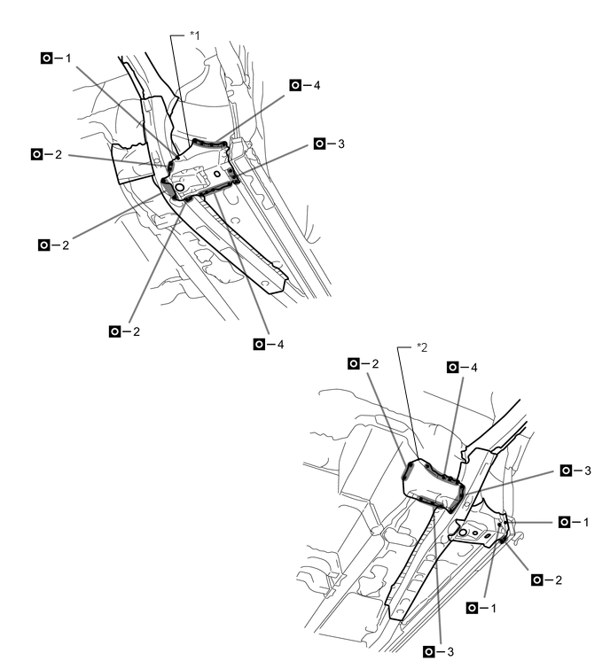
| *1 | TORQUE BOX SUB-ASSEMBLY FRONT | *2 | FRONT SIDE MEMBER REINFORCE SUB-ASSEMBLY NO.2 |
After welding, apply body sealer and undercoating to the corresponding parts. (See the painting/coating)
After applying the top coat, apply anti-rust agent to the internal panel portion of the closed section structural weld points.