HEATING / AIR CONDITIONING AIR CONDITIONING SYSTEM DETAILS COOLER COMPRESSOR
CONSTRUCTION
ESB27C Type Compressor (HV Models)
An ESB27C type compressor assembly with motor that is driven by a motor is used. The basic construction and operation of this compressor are the same as an ordinary scroll compressor, except that it is driven by an electric motor.
The compressor assembly with motor consists of a spirally wound fixed scroll and rotating scroll that form a pair, an injection block, a brushless motor, an oil separator, a motor shaft and an air conditioning inverter.
An air conditioning inverter is integrated with the compressor assembly with motor. This inverter operates the compressor on HV battery voltage. As a result, the air conditioning system is actuated without depending on the operation of the engine, achieving a comfortable air conditioning system and low fuel consumption.
The fixed scroll is integrated with the housing. Because the rotation of the shaft causes the rotating scroll to revolve while maintaining the same posture, the volume of the space that is partitioned by both scrolls varies to perform the suction, compression and discharge of the refrigerant gas. Locating the suction port directly above the scrolls enables direct suction, achieving improved suction efficiency. Containing a built-in oil separator, the compressor is able to separate the compressor oil that is intermixed with the refrigerant and circulates in the refrigerant cycle, achieving reduction in the oil circulation rate.
Low-moisture permeation hoses are used for the suction and discharge hoses of the compressor in order to minimize the entry of moisture into the refrigerant cycle.
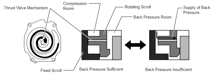
A thrust valve mechanism is used as a back pressure adjustment method, which enables appropriate adjustment of back pressure to reduce excessive pressure and improve efficiency.
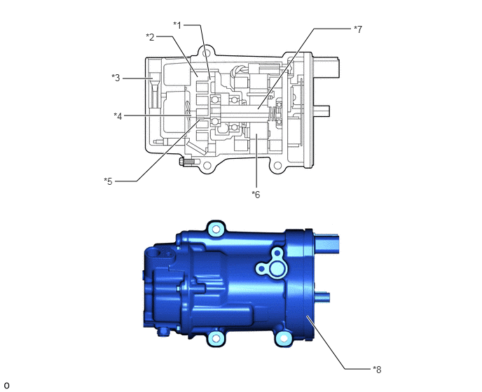
| *1 | Rotating Scroll | *2 | Fixed Scroll |
| *3 | Oil Separator | *4 | Discharge Port |
| *5 | Thrust Valve | *6 | Brushless Motor |
| *7 | Motor Shaft | *8 | Air Conditioning Inverter |
- CAUTION:
-
In order to ensure the proper insulation of the internal high-voltage portion of the compressor assembly with motor and the compressor housing, this model has used a compressor oil (ND11) with a high level of insulation performance. Therefore, never use a compressor oil other than ND11 type compressor oil or its equivalent.
7SES17C Type Compressor (Gasoline Models)
The 7SES17C external control type continuously variable capacity compressor assembly with pulley is used in consideration of reduced energy consumption.
A discharge passage is provided in the control valve so that liquid refrigerant will be discharged if an excessive amount of the refrigerant is in the control valve. This significantly reduces the amount time required to discharge liquid refrigerant, largely contributing to quick cooling performance.
A shaft oil separator mechanism is provided in the compressor assembly with pulley to separate oil from the refrigerant. This allows a large part of the refrigerant to be circulated in the air conditioning system, enhancing cooling efficiency.
A variable suction side throttle is provided in the compressor assembly with pulley to partially close the suction passage of the refrigerant. This allows the suction passage to be partially closed when driving with the refrigerant volume controlled such as when accelerating or driving at high speeds, helping to reduce pulsation noises when introducing refrigerant.
This compressor assembly with pulley consists of a Damper Limiter (DL) type pulley, shaft, lug plate, swash plate, piston, shoe, crank chamber, cylinder and solenoid valve.
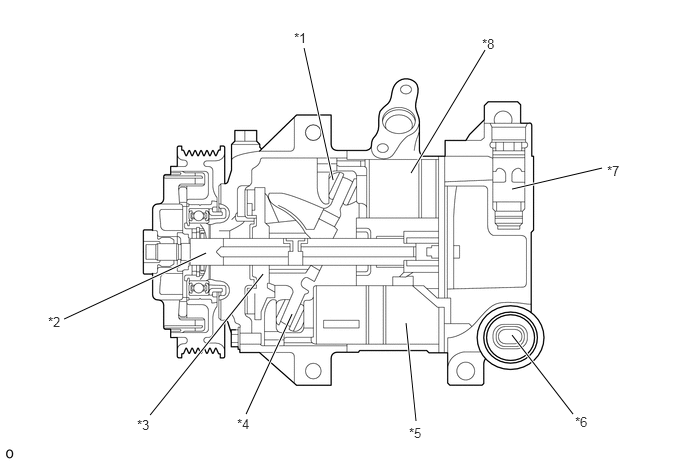
| *1 | Shoe | *2 | Shaft |
| *3 | Lug Plate | *4 | Swash Plate |
| *5 | Cylinder | *6 | Ps Control Valve |
| *7 | Variable Suction Side Throttle | *8 | Piston |
Structure of External Control type Continuously Variable Capacity Compressor
When the shaft rotates, the swash plate is rotated via the lug plate, which is directly connected to the shaft. This rotational motion of the swash plate is converted to piston movement for introducing, compressing and discharging the refrigerant. Variable control of capacity is to control pressure in the swash plate chamber. This pressure change changes the tilt angle of the swash plate, thereby changing the piston stroke to control the discharge volume of the refrigerant. With the external control type continuously variable capacity compressor, control current applied to the Ps control valve is steplessly changed. This allows for a wider range of discharge volume control, contributing to enhanced cabin comfort and reduced energy consumption.
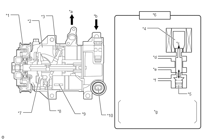
| *1 | Pulley | *2 | Swash Plate Chamber |
| *3 | Shoe | *4 | Coil |
| *5 | Bellows | *6 | Ps Control Valve |
| *7 | Lug Plate | *8 | Swash Plate |
| *9 | Piston | *10 | Ps Control Valve |
| *a | Discharge Pressure | *b | Suction Pressure |
| *c | Electromagnetic Force | *d | Suction Pressure (Ps) |
| *e | Discharge Pressure (Pd) | *f | Pressure in Swash Plate Chamber (Pc) |
| *g | Based on the duty cycle controlled application of power to the coil in the Ps control valve, electromagnetic force is controlled to expand and compress the bellows, changing the internal pressure of the swash plate. | - | - |
Damper Limiter (DL) Type Pulley
This pulley contains a damper to absorb the torque fluctuations of the engine and a limiter mechanism to protect the drive belt in case the compressor locks. In the event that the compressor locks, the limiter mechanism causes the spoke portion of the pulley to break, separating the pulley from the compressor assembly with pulley.
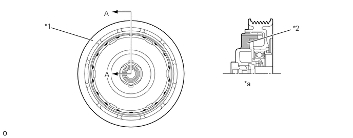
| *1 | Damper Limiter (DL) Type Pulley | *2 | Damper |
| *a | A - A Cross Section | - | - |
OPERATION
ESB27C Type Compressor (HV Models)
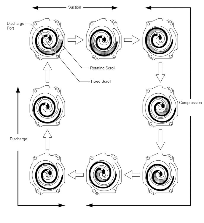
The compressor assembly with motor performs suction, compression and discharge of refrigerant gas as described in the table below.
| Stroke | Operation |
|---|---|
| Suction | As the capacity of the compression chamber, which is created between the rotating scroll and the fixed scroll, increases in accordance with the revolution of the rotating scroll, refrigerant gas is drawn in from the intake port. |
| Compression | As the movable scroll orbits eccentrically, the volume of the high-pressure chamber decreases. With this, the pulled in refrigerant is steadily compressed and discharged into the center of the fixed scroll. Partway through the compression process, partially compressed refrigerant is injected. As the movable scroll orbits eccentrically, the gas injection port is isolated from the compression chamber and the flow of injected refrigerant stops. The compression of the refrigerant is complete after the movable scroll completes 2 orbits. |
| Discharge | When the compression of the refrigerant gas is completed and the refrigerant pressure becomes high, the refrigerant gas discharges through the discharge port located in the center of the fixed scroll by pushing the discharge valve. |
Thrust Valve Mechanism Operation
If the back pressure is less than the value required, pressure is supplied from the compression room to the back pressure room using the thrust valve installed in the rotating scroll to adjust the back pressure to the appropriate value.
7SES17C Type Compressor (Gasoline Models)
External Control Type Continuously Variable Capacity Compressor Operation
Operation when capacity increase is necessary
If the heat load has been increased or if the volume needs to be increased such as when acceleration control has finished, the current applied to the PS control valve coil is increased. The electromagnetic force will then become larger than the spring force and act in the opposite direction of the coil, closing the Pd to Pc passage. As a result of this, high pressure will be shut off and the pressure in the swash plate chamber will gradually decrease. Therefore, the sum of the pressure applied to the left side of the piston (Pc), spring force (Fs) and reaction force from the lug plate (FL) becomes smaller than the sum of the force applied to the right side of the piston (P1 + ... + P6), and the piston is moved to the left, increasing the tilt angle of the swash plate. This results in larger piston strokes. (The illustration is of when the discharge volume is large.)
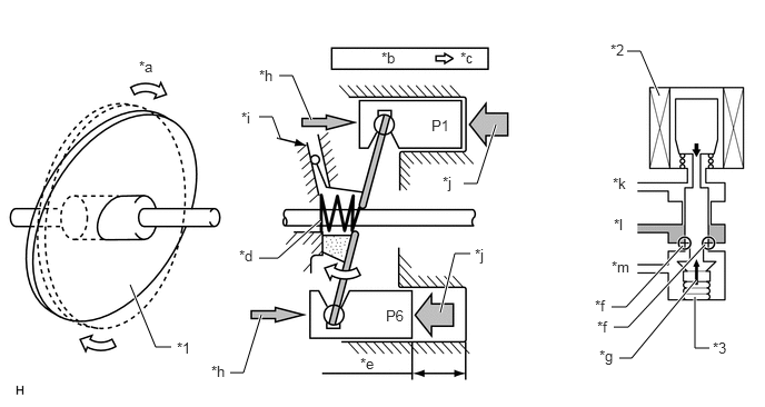
| *1 | Swash Plate | *2 | Coil |
| *3 | Bellows | - | - |
| *a | Amount of Swash Plate Tilt Increases | *b | Pd to Pc Passage (Opened) |
| *c | Pc Decreased | *d | Spring (Fs) |
| *e | Large Stroke | *f | Pd to Pc Passage (Closed) |
| *g | Spring Force | *h | (Pc+Fs+FL) |
| *i | Lug Plate (FL) | *j | (P1 + ... + P6) |
| *k | Suction Pressure (Ps) | *l | Discharge Pressure (Pd) |
| *m | Pressure in Swash Plate Chamber (Pc) | - | - |
Operation when capacity decrease is necessary
If the heat load has been decreased or if the volume needs to be decreased such as when accelerating or driving at high speeds, the current applied to the Ps control valve coil is decreased. The electromagnetic force will then become smaller than the spring force and act in the same direction of the coil, opening the Pd to Pc passage. As a result of this, high pressure (Pd) will be introduced into the swash plate chamber and the pressure in the swash plate chamber will gradually increase. Therefore, the sum of the pressure applied to the left side of the piston (Pc), spring force (Fs) and reaction force from the lug plate (FL) becomes larger than the sum of the force applied to the right side of the piston (P1 + ... + P6), and the piston is moved to the right, decreasing the tilt angle of the swash plate. This results in smaller piston strokes. (The illustration is of when the discharge volume is small.)
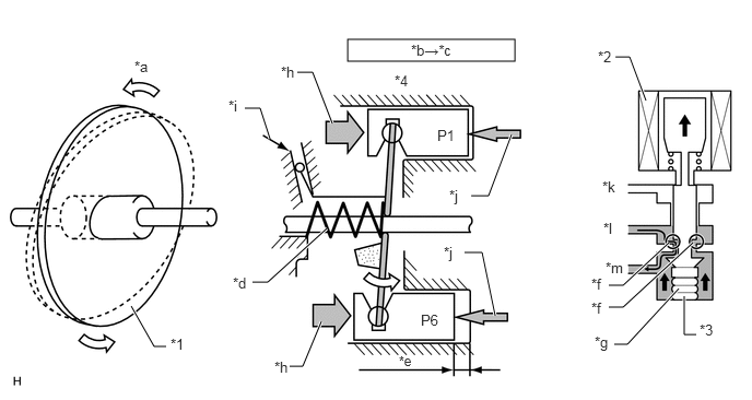
| *1 | Swash Plate | *2 | Coil |
| *3 | Bellows | *4 | Piston |
| *a | Amount of Swash Plate Tilt Increases | *b | Pd to Pc Passage (Opened) |
| *c | Pc Decreased | *d | Spring (Fs) |
| *e | Large Stroke | *f | Pd to Pc Passage (Closed) |
| *g | Spring Force | *h | (Pc+Fs+FL) |
| *i | Lug Plate (FL) | *j | (P1 + ... + P6) |
| *k | Suction Pressure (Ps) | *l | Discharge Pressure (Pd) |
| *m | Pressure in Swash Plate Chamber (Pc) | - | - |
Variable CS Valve
The variable capacity compressor sends compressed control gas from the Ps control valve to the swash plate chamber to change the tilt angle of the swash plate, thereby changing the compressor capacity. After control, control gas flows back from the swash plate chamber to the suction chamber, and is then compressed again. Conventionally, the refrigerant was sent back from the swash plate chamber to the suction chamber through a fixed orifice.
The variable CS valve is partially closed only when variable operation is performed, which requires control gas, allowing for variable operation using the minimum amount of control gas. By reducing the amount of control gas, compressor power is reduced.
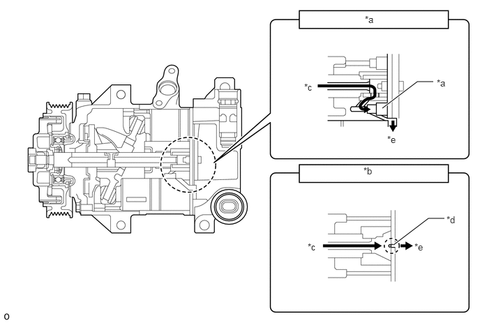
| *a | Variable CS Valve | *b | Reference: Fixed Orifice Valve |
| *c | from Swash Plate Chamber | *d | Fixed Orifice Valve |
| *e | to Suction Chamber | - | - |

|
Control Gas | - | - |
Shaft Oil Separator
For the conventional cooler compressor assembly, oil was mixed in with the suction refrigerant to ensure sliding performance of the parts. However, when the refrigerant was discharged from the cooler compressor assembly, oil, which did not contribute to refrigerant efficiency, was circulated in the air conditioning system, adversely affecting the cooling efficiency. For the 7SES17C type cooler compressor assembly, an oil separator is provided to the shaft so that a large amount of the oil is kept in the cooler compressor assembly. This greatly enhances the cooling performance and helps to reduce the power consumption of the air conditioning system.
For the conventional cooler compressor assembly, refrigerant was sent back from the swash plate chamber through the oil return portion, located on the tip of the shaft, to the suction chamber so that oil containing refrigerant gas was sent back to the suction chamber and the amount of circulated oil was increased.
For the shaft oil separator, an oil return portion is provided in the area between the swash plate and lug plate, in which a small amount of oil is circulated, in order to send back refrigerant gas containing only a small amount of oil to the suction chamber. This ensures that a large amount of oil is kept in the swash plate chamber, which contains sliding parts, thereby reducing the amount of circulated oil.
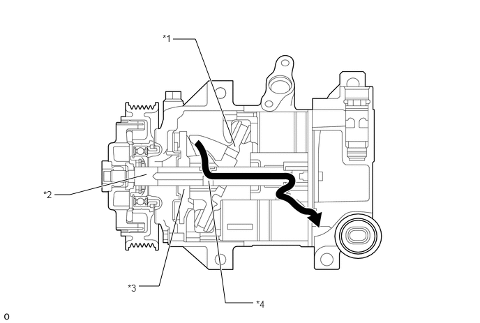
| *1 | Swash Plate | *2 | Shaft |
| *3 | Lug Plate | *4 | Shaft Oil Separator |
|
|
Refrigerant Gas | - | - |
Variable Suction Side Valve
For the conventional variable suction side compressor, a pulsation dampener was used in the suction passage to counter the suction pulsation noises generated when controlling the refrigerant volume. For the newly adopted cooler compressor assembly, a variable suction side valve, which enables the adjustment of refrigerant flow in the suction passage is used. This valve is closed in accordance with the refrigerant flow when controlling the refrigerant volume, helping to reduce suction pulsation noises. Also, with the maximum volume of refrigerant, the variable suction side valve is fully opened to prevent the suction resistance of the cooler compressor assembly from being increased due to the throttle.
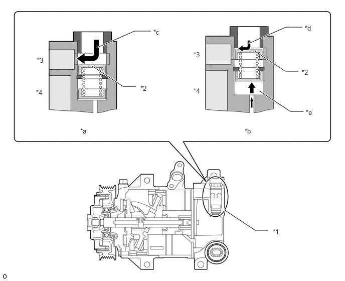
| *1 | Variable Suction Side Throttle | *2 | Spool Valve |
| *3 | Suction Chamber | *4 | Discharge Chamber |
| *a | With Maximum Volume of Refrigerant | *b | With Controlled Volume of Refrigerant |
| *c | Refrigerant Flow: Large | *d | Refrigerant Flow: Small |
| *e | Pressure from Swash Plate Chamber | - | - |