NM3620E
_51
Engine / Hybrid System
_075753
A25A-FKS EMISSION CONTROL
_0371202
EXHAUST GAS RECIRCULATION SYSTEM
DE
DETAILS
F
A25A-FKS EMISSION CONTROL EXHAUST GAS RECIRCULATION SYSTEM DETAILS EGR VALVE AND EGR COOLER
CONSTRUCTION
a.
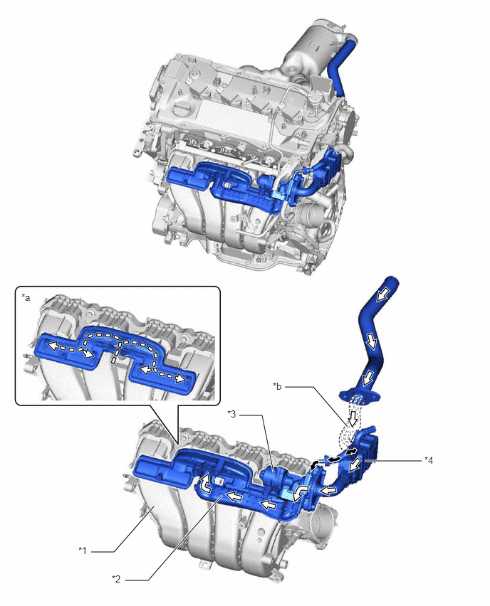
A stepper motor type EGR valve assembly with excellent response characteristics is used to precisely control the EGR gas flow amount.
b.
Circulating coolant to the EGR valve assembly ensures cooling performance of the valve sliding parts and the stepper motor.
c.
An EGR delivery chamber is built into the intake manifold.
d.
The amount of EGR gas flow is controlled by the EGR valve assembly and an EGR distribution path with a tournament tree structure is built into the intake manifold to distribute EGR to each cylinder evenly.
e.
EGR gas discharged from the exhaust manifold is directed through the cylinder head sub-assembly in order to cool the EGR gas.
1.333,8.083 1.667,8.083
1.667,8.083 2.25,7.417
true
1.833,8.5 2.167,8.5
2.167,8.5 3.25,7.25
true
3.5,6.083 3.833,6.083
3.833,6.083 4,6.917
true
5.333,6.75 6.167,6.75
true
4.167,5.667 4.583,5.667
4.583,5.667 5.083,6.25
true
1.146,7.979 1.333,8.177
0.188,0.198
10
false
*1
1.635,8.396 1.823,8.594
0.188,0.198
10
false
*2
3.323,5.979 3.51,6.177
0.188,0.198
10
false
*3
6.208,6.656 6.396,6.854
0.188,0.198
10
false
*4
0.313,4.271 0.5,4.469
0.188,0.198
10
false
*a
3.99,5.573 4.177,5.771
0.188,0.198
10
false
*b
| *1 | Intake Manifold | *2 | EGR Pipe |
| *3 | EGR Valve Assembly | *4 | EGR Cooler Assembly |
| *a | EGR Distribution Path (Tournament Tree Structure) | *b | Cylinder Head Sub-assembly Passage |

|
Engine Coolant Flow | 
|
Exhaust Gas Flow |