NM3620E
_51
Engine / Hybrid System
_075755
A25A-FKS COOLING
_0371220
COOLANT FLOW
GE
GENERAL
F
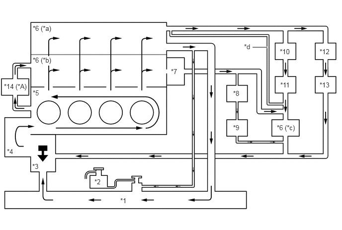
A25A-FKS COOLING COOLANT FLOW GENERAL SYSTEM DIAGRAM
5.292,0.99 5.604,0.99
true
2.521,4.125 2.833,4.281
0.313,0.156
10
false
*1
1.979,3.729 2.292,3.885
0.313,0.156
10
false
*2
0.677,3.406 0.99,3.563
0.313,0.156
10
false
*3
0.146,3.094 0.458,3.25
0.313,0.156
10
false
*4
0.688,1.865 1,2.021
0.313,0.156
10
false
*5
0.688,0.51 1.219,0.708
0.531,0.198
10
false
*6 (*a)
3.583,1.417 3.896,1.573
0.313,0.156
10
false
*7
4.885,1.875 5.198,2.031
0.313,0.156
10
false
*8
4.885,2.594 5.198,2.75
0.313,0.156
10
false
*9
5.865,1 6.333,1.156
0.469,0.156
10
false
*10
5.875,1.698 6.344,1.854
0.469,0.156
10
false
*11
6.698,1 7.01,1.229
0.313,0.229
10
false
*12
6.698,1.698 7.031,1.917
0.333,0.219
10
false
*13
0.083,1.729 0.729,1.948
0.646,0.219
10
false
*14 (*A)
5.115,0.896 5.427,1.052
0.313,0.156
10
false
*d
0.688,1.177 1.219,1.375
0.531,0.198
10
true
*6 (*b)
5.802,2.594 6.333,2.792
0.531,0.198
10
false
*6 (*c)
| *A | Models with Engine Oil Cooler (Oil Cooler Assembly) | - | - |
| *1 | Radiator Assembly | *2 | Radiator Reserve Tank Assembly |
| *3 | Water Inlet with Thermostat Sub-assembly | *4 | Engine Water Pump Assembly (Water Inlet Housing with Water Pump Sub-assembly) |
| *5 | Cylinder Block Sub-assembly | *6 | Cylinder Head Sub-assembly |
| *7 | EGR Cooler Assembly | *8 | EGR Valve Assembly |
| *9 | Throttle Body with Motor Assembly | *10 | Flow Shutting Valve (for Heater Control) (Water By-pass Hose Assembly) |
| *11 | Heater Radiator Unit Sub-assembly | *12 | Flow Shutting Valve (for ATF Control) (No. 1 Water By-pass Hose) |
| *13 | ATF Warmer (Transmission Oil Cooler) | *14 | Engine Oil Cooler (Oil Cooler Assembly) |
| *a | Upper Water Jacket | *b | Lower Water Jacket |
| *c | Sub Water Jacket | *d | Passage Inside Water By-pass Outlet Sub-assembly |