BATTERY / CHARGING CHARGING SYSTEM(for HV Model) DETAILS BATTERY SENSOR
CONSTRUCTION
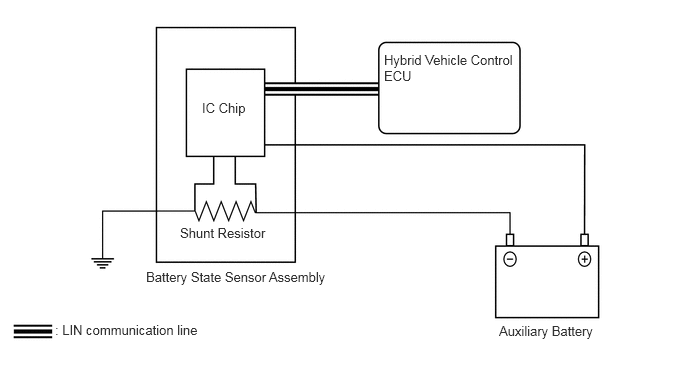
The battery state sensor assembly is installed to the negative (-) battery terminal side of the auxiliary battery. The battery state sensor assembly calculates the current, voltage, temperature, SOC (battery charging rate) and SOH (battery deterioration level), and sends signals to the hybrid vehicle control ECU via the LIN communication.
To detect the current of the auxiliary battery, a shunt resistor installed inside the battery state sensor assembly is used to convert the voltage that is generated in the shunt resistor due to the battery charge and discharge current and calculate the current.
The auxiliary battery temperature is calculated from the resistance value of the thermistor built into the battery state sensor assembly.