Home › Drivetrain › K120 (MULTIDRIVE / CVT) › CVT SYSTEM
NM3620E _52 Drivetrain _076476 K120 MULTIDRIVE / CVT _0375429 CVT SYSTEM DE DETAILS F

K120 MULTIDRIVE / CVT  CVT SYSTEM  DETAILS  VALVE BODY UNIT  


CONSTRUCTION


a.

The valve bodies are heat treated to suppress deformation, allowing oil pump capacity to be reduced.
X140517C01
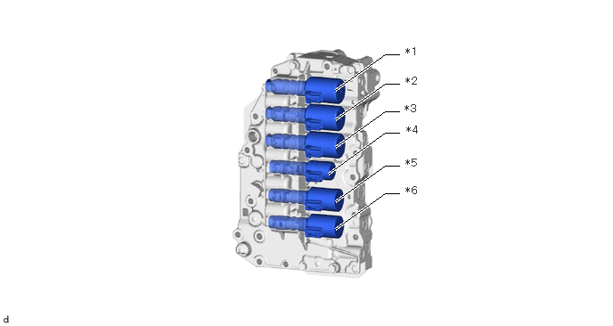
3.917,1.396 4.5,0.979 4.5,0.979 4.667,0.979 true 3.917,1.052 4.5,0.635 4.5,0.635 4.667,0.635 true 3.917,1.719 4.5,1.302 4.5,1.302 4.667,1.302 true 3.917,2.354 4.5,1.938 4.5,1.938 4.667,1.938 true 3.917,2.677 4.5,2.26 4.5,2.26 4.667,2.26 true 3.833,2.031 4.5,1.552 4.5,1.552 4.667,1.552 true 4.74,0.531 5.052,0.688 0.313,0.156 10 false *1 4.74,0.875 5.052,1.031 0.313,0.156 10 false *2 4.729,1.198 5.042,1.354 0.313,0.156 10 false *3 4.75,1.448 5.063,1.604 0.313,0.156 10 false *4 4.74,1.833 5.052,1.99 0.313,0.156 10 false *5 4.74,2.156 5.052,2.313 0.313,0.156 10 false *6
*1 Linear Solenoid Valve SLG *2 Linear Solenoid Valve SL1
*3 Linear Solenoid Valve SL2 *4 Linear Solenoid Valve SLU
*5 Linear Solenoid Valve SLP *6 Linear Solenoid Valve SLS


X140928C01
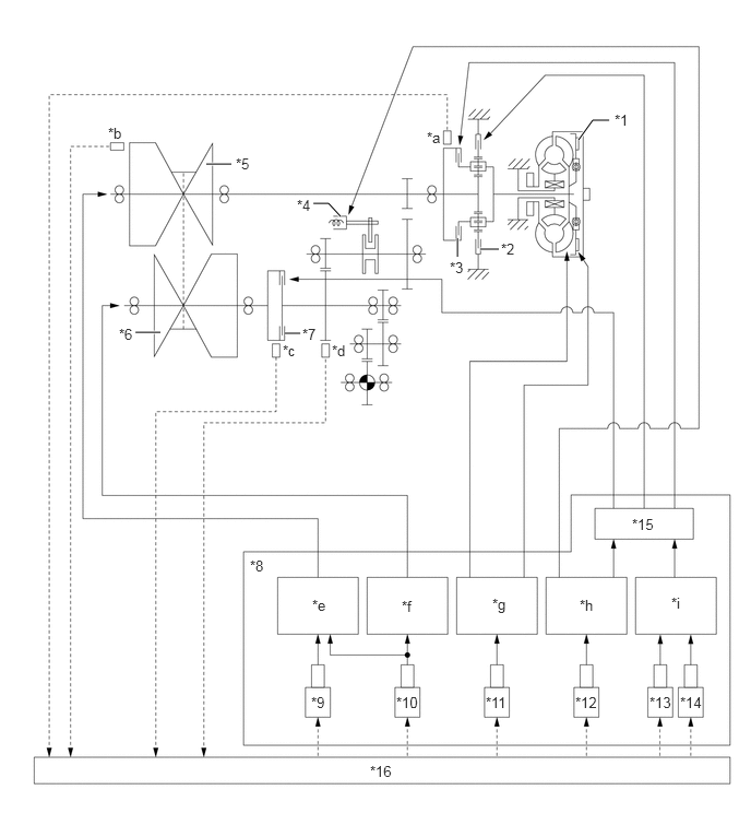
4.583,2.375 4.76,2.375 true 4.365,2.271 4.365,2.448 true 2.719,3.177 2.865,3.177 true 1.292,3.167 1.531,3.167 true 1.969,1.563 2.208,1.563 true 2.99,1.938 3.135,1.938 3.135,1.938 3.25,2.063 true 5.521,1.333 5.656,1.146 5.656,1.146 5.813,1.146 true 5.865,1.063 6.177,1.219 0.313,0.156 10 false *1 4.781,2.292 5.094,2.448 0.313,0.156 10 false *2 4.292,2.469 4.604,2.625 0.313,0.156 10 false *3 2.833,1.875 3.146,2.031 0.313,0.156 10 false *4 2.25,1.479 2.563,1.635 0.313,0.156 10 false *5 1.135,3.104 1.448,3.26 0.313,0.156 10 false *6 2.885,3.104 3.198,3.26 0.313,0.156 10 false *7 2.385,5.313 2.698,5.469 0.313,0.156 10 false *8 2.969,6.615 3.281,6.771 0.313,0.156 10 false *9 3.781,6.615 4.25,6.771 0.469,0.156 10 false *10 4.635,6.615 5.104,6.771 0.469,0.156 10 false *11 5.49,6.615 5.958,6.771 0.469,0.156 10 false *12 6.198,6.615 6.667,6.771 0.469,0.156 10 false *13 6.49,6.615 6.958,6.771 0.469,0.156 10 false *14 6.031,4.917 6.5,5.073 0.469,0.156 10 false *15 3.531,7.271 4,7.427 0.469,0.156 10 false *16 4.073,1.229 4.385,1.385 0.313,0.156 10 false *a 1.031,1.188 1.344,1.344 0.313,0.156 10 false *b 2.698,3.26 3.01,3.417 0.313,0.156 10 false *c 3.167,3.26 3.479,3.417 0.313,0.156 10 false *d 2.979,5.688 3.292,5.844 0.313,0.156 10 false *e 3.833,5.698 4.146,5.854 0.313,0.156 10 false *f 4.698,5.677 5.021,5.865 0.323,0.188 10 false *g 5.531,5.688 5.844,5.844 0.313,0.156 10 false *h 6.406,5.667 6.719,5.823 0.313,0.156 10 false *i
*1 Lock-up Clutch *2 B1 Brake
*3 C1 Clutch *4 Pressure Servo
*5 Primary Pulley *6 Secondary Pulley
*7 C2 Clutch *8 Valve Body
*9 Linear Solenoid Valve SLP *10 Linear Solenoid Valve SLS
*11 Linear Solenoid Valve SLU *12 Linear Solenoid Valve SLG
*13 Linear Solenoid Valve SL2 *14 Linear Solenoid Valve SL1
*15 Manual Valve *16 Transmission Control ECU
*a NC1 *b NT
*c NSS *d NOUT
*e Vehicle Speed Control *f Belt Clamping Pressure Control
*g Lock-up Control *h Pressure Servo Control/Brake Pressure Control
*i Clutch Control - -


OPERATION


a.

Belt Clamping Pressure Control Circuit

i.

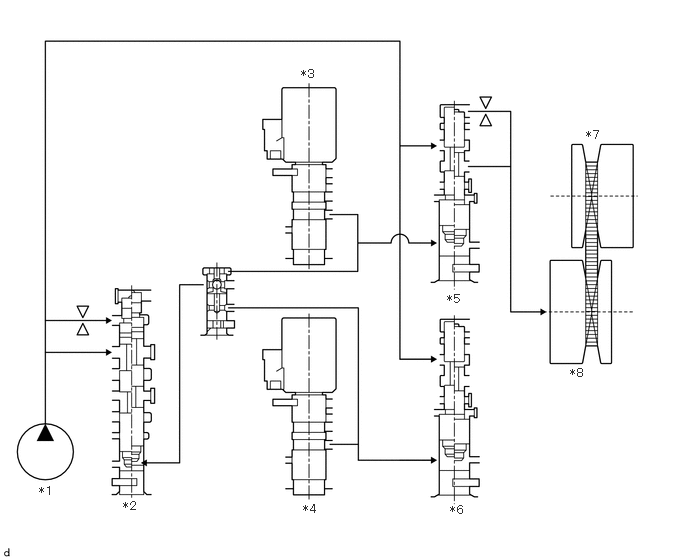
To ensure the proper control of the belt clamping pressure necessary for transmitting torque, the system controls the hydraulic pressure applied to the secondary pulley. The transmission valve body assembly is provided with a dedicated hydraulic pressure circuit for belt clamping pressure control. This circuit optimally controls the hydraulic pressure applied to the secondary pulley, achieving superior torque transmission performance.
X140526C01
0.406,5.042 0.719,5.198 0.313,0.156 10 false *1 1.281,5.198 1.594,5.354 0.313,0.156 10 false *2 3.135,0.698 3.448,0.854 0.313,0.156 10 false *3 3.156,5.229 3.469,5.385 0.313,0.156 10 false *4 4.656,3.042 4.969,3.198 0.313,0.156 10 false *5 4.688,5.24 5,5.396 0.313,0.156 10 false *6 6.104,1.333 6.417,1.49 0.313,0.156 10 false *7 5.938,3.813 6.25,3.969 0.313,0.156 10 false *8
*1 Oil Pump Assembly *2 Primary Regulator Valve
*3 Linear Solenoid Valve SLS (for Secondary Pulley Control) *4 Linear Solenoid Valve SLP (for Primary Pulley Control)
*5 Secondary Sheave Control Valve *6 Primary Sheave Control Valve
*7 Primary Pulley *8 Secondary Pulley


b.

Pulley Ratio Control Circuit

i.

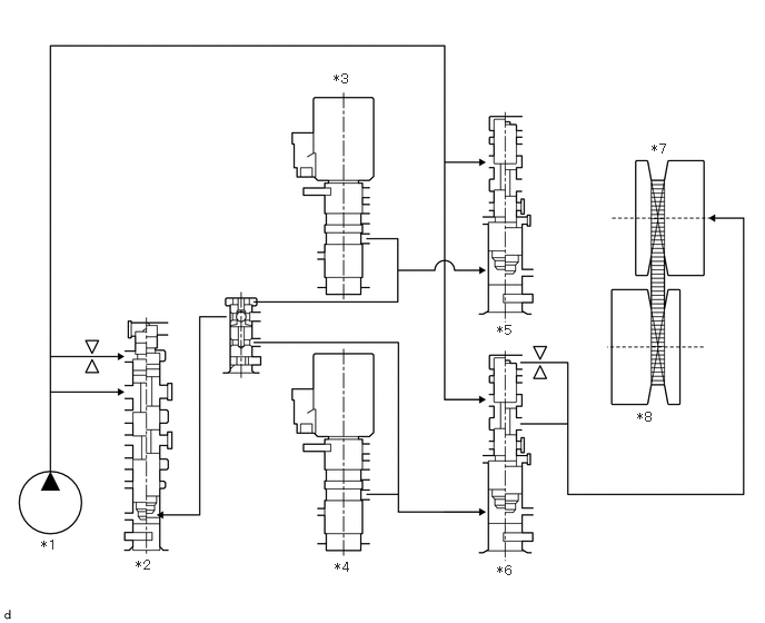
Pulley ratio control is performed by controlling the inflow and outflow of the CVT fluid to the primary pulley. Separate hydraulic circuits are provided for acceleration (fluid inflow) and deceleration (fluid outflow) in order to provide fine-tuned control and a high level of reliability.
X140568C01
0.385,5.031 0.625,5.26 0.24,0.229 10 false *1 1.271,5.219 1.51,5.406 0.24,0.188 10 false *2 3.125,0.667 3.385,0.865 0.26,0.198 10 false *3 3.135,5.24 3.385,5.427 0.25,0.188 10 false *4 4.656,3.021 4.896,3.208 0.24,0.188 10 false *5 4.656,5.271 4.906,5.479 0.25,0.208 10 false *6 6.104,1.323 6.354,1.51 0.25,0.188 10 false *7 5.969,3.833 6.219,4.042 0.25,0.208 10 false *8
*1 Oil Pump Assembly *2 Primary Regulator Valve
*3 Linear Solenoid Valve SLS (for Secondary Pulley Control) *4 Linear Solenoid Valve SLP (for Primary Pulley Control)
*5 Secondary Sheave Control Valve *6 Primary Sheave Control Valve
*7 Primary Pulley *8 Secondary Pulley


c.

Lock-up Control

i.

Lock-up control is performed by controlling the oil pressure of the lock-up clutch. The lock up control valve and linear solenoid valve SLU are provided to control the lock-up clutch.
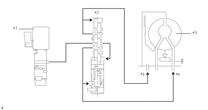
X140566C01
0.646,1 1.156,1 true 6.063,1.156 6.573,1.156 true 0.458,0.906 0.771,1.063 0.313,0.156 10 false *1 3.26,0.365 3.563,0.573 0.302,0.208 10 false *2 6.635,1.063 6.948,1.219 0.313,0.156 10 false *3 4.844,2.5 5.156,2.656 0.313,0.156 10 false *a 6.063,2.5 6.375,2.656 0.313,0.156 10 false *b
*1 Linear Solenoid Valve SLU *2 Lock-up Control Valve
*3 Torque Converter Assembly - -
*a OFF *b ON