Home › Vehicle Exterior › EXTERIOR PANELS / TRIM › BODY STRUCTURE
NM3620E _59 Vehicle Exterior _077728 EXTERIOR PANELS / TRIM _0377329 BODY STRUCTURE DE DETAILS F

EXTERIOR PANELS / TRIM  BODY STRUCTURE  DETAILS  BODY SHELL  


CONSTRUCTION


a.

Body Shell

i.

The position of the body's structural parts is optimized, optimized connection methods are used and reinforcing materials are provided, creating a lightweight body structure with high rigidity and ensuring driving stability.


b.

The following structure is provided to increase the rigidity of the front body, increasing responsiveness to driver steering wheel operations and achieving superior driving stability.

i.

Outrigger is provided for connection area of side member frame (*1 in illustration).


ii.

Connection strength of side panel outer No. 2 and surrounding panels is strengthened (*2 in illustration).


iii.

Thickness of front spring support plate is increased (*3 in illustration).
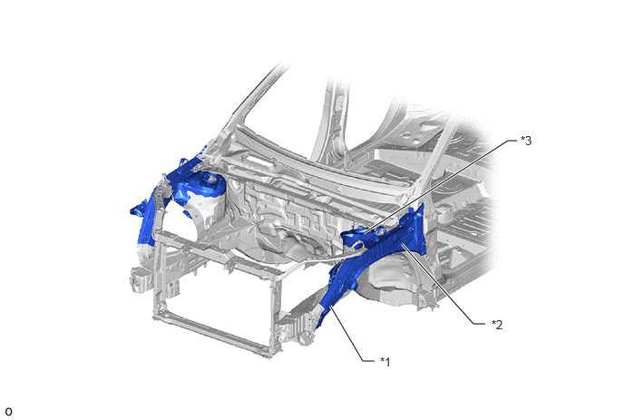
Front Body (This illustration is an example only.)
V123248C01
3.792,3.51 4.167,4.146 4.167,4.146 4.302,4.146 true 4.615,2.802 5.438,3.719 5.438,3.719 5.573,3.719 true 4.177,2.677 5.833,1.615 5.833,1.615 5.938,1.615 true 4.365,4.073 4.677,4.229 0.313,0.156 10 false *1 5.646,3.646 5.958,3.802 0.313,0.156 10 false *2 5.979,1.531 6.292,1.688 0.313,0.156 10 false *3
*1 Front Fender Apron Gusset Lower LH *2 Side Panel Outer No. 2 LH
*3 Front Spring Support Plate LH - -


iv.

The frame lines of the cowl ventilator panel sub-assembly are straightened and made closed cross-sections to increase the rigidity of the left and right suspension tower connections, achieving superior driving stability.
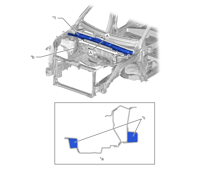
Cowl Ventilator Panel Sub-assembly (This illustration is an example only.)
V123247C01
1.896,3.542 5.354,5.667 3.458,2.125 2,0.625 2.167,0.625 2.167,0.625 2.719,1.208 true 2.573,4.917 4.896,4.104 4.896,4.104 4.604,4.708 true 1.24,1.969 1.406,1.969 1.406,1.969 3.083,1.531 true 3.667,1.167 3.823,1.365 0.156,0.198 10 false A 3.094,1.74 3.219,1.917 0.125,0.177 10 false A 3.458,5.396 3.667,5.563 0.208,0.167 10 false *a 1.813,0.531 1.979,0.708 0.167,0.177 10 false *1 4.917,3.979 5.104,4.156 0.188,0.177 10 false *c 1.063,1.885 1.25,2.063 0.188,0.177 10 false *b
*1 Cowl Ventilator Panel Sub-assembly - -
*a A - A Cross Section *b Straight
*c Closed Cross-sections - -


c.

Floor

i.

The framework connection area of the front floor reinforcement sub-assembly uses a continuous flange, discontinuing the cutouts used in the conventional structure and increasing the rigidity of the framework connection. As a result, superior driving stability is achieved.
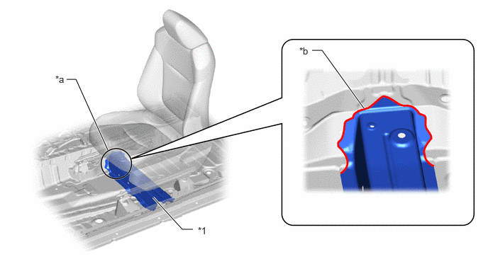
Continuous Flange Structure (This illustration is an example only.)
V123250C01
5.344,1.594 4.729,0.74 4.729,0.74 4.583,0.74 true 2.25,2.906 2.677,3.375 2.677,3.375 2.833,3.375 true 1.583,2.208 1.115,1.167 1.115,1.167 0.979,1.167 true 2.906,3.313 3.219,3.51 0.313,0.198 10 false *1 0.813,1.083 1.125,1.281 0.313,0.198 10 false *a 4.396,0.667 4.708,0.865 0.313,0.198 10 false *b
*1 Front Floor Reinforcement Sub-assembly LH - -
*a Front Floor Reinforcement Sub-assembly Frame Connection Area *b Continuous Flange


ii.

The front seat rail installation area is directly installed to the body instead of passing through the seat rail bracket used in the conventional vehicle. As a result, floor body rigidity is increased to achieve superior driving stability.
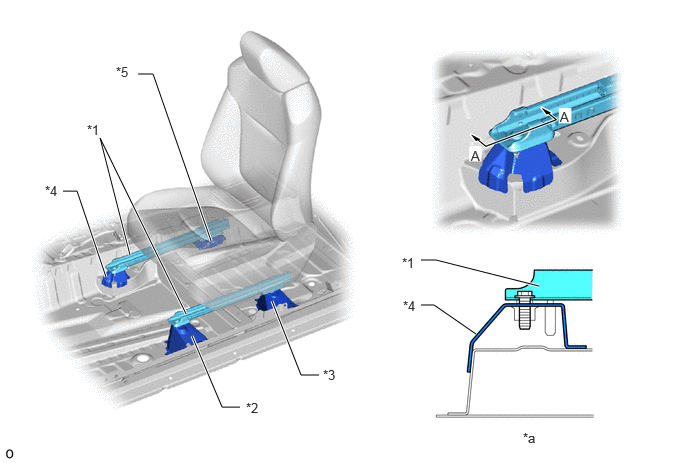
Front Seat Rail Installation Area (This illustration is an example only.)
V123251C01
2,3.5 2.313,4.24 2.313,4.24 2.5,4.24 true 1.938,3.271 1.042,1.438 1.042,1.438 1.354,2.656 true 2.833,3.135 3.135,3.906 3.135,3.906 3.323,3.906 true 4.385,3.177 4.521,3.177 4.521,3.177 4.958,3.479 true 4.385,2.708 4.542,2.708 4.542,2.708 5.615,2.979 true 1.104,2.885 0.802,1.99 0.802,1.99 0.656,1.99 true 2.198,2.51 1.594,0.771 1.594,0.771 1.438,0.771 true 5.833,1.135 5.99,1.333 0.156,0.198 10 false A 4.906,1.542 5.063,1.74 0.156,0.198 10 false A 5.448,4.479 5.604,4.677 0.156,0.198 10 false *a 0.906,1.271 1.063,1.469 0.156,0.198 10 false *1 2.563,4.167 2.719,4.365 0.156,0.198 10 false *2 3.365,3.823 3.521,4.021 0.156,0.198 10 false *3 4.198,3.104 4.354,3.302 0.156,0.198 10 false *4 4.188,2.656 4.344,2.854 0.156,0.198 10 false *1 0.469,1.906 0.625,2.104 0.156,0.198 10 false *4 1.208,0.667 1.365,0.865 0.156,0.198 10 false *5
*1 Front Seat Rail *2 Front Floor Reinforcement Sub-assembly
*3 Rear Step Plate Sub-assembly *4 Front Seat Mounting Bracket Inside RH
*5 Front Seat Inside Mounting Bracket Front RH - -
*a A - A Cross Section - -


d.

Side Body

i.

The connection rigidity of each corner of the door opening is increased, achieving superior driving stability.

·

The roof side rail upper and roof side rail outer No. 2 are positioned so that they extend to the front of the quarter body pillar (A in illustration).

·

The connecting length of the rail and the upper part of the center body pillar is made longer (B in illustration).

·

The wall of the center body pillar inner wraps around the upper part of the rocker, greatly increasing the area of the connection area (C in illustration).

·

Structural adhesive* is used for the corner of the quarter body pillar (*g in illustration).

HINT:

*: Compared to conventional spot welding where panels are only connected at certain points, this adhesive is used together with welds to connect body surfaces, minimizing bending and warping to maximize rigidity.
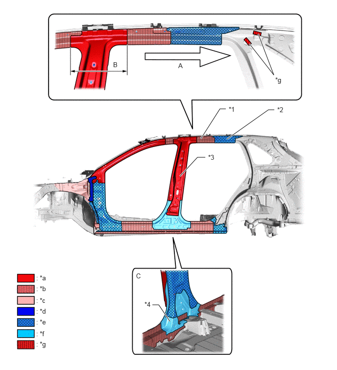

Side Body (This illustration is an example only.)
V123252C01
3.823,3.75 4.198,3.344 4.198,3.344 4.365,3.344 true 4.802,2.313 4.677,2.313 4.677,2.313 4.271,2.948 true 5.833,2.333 5.708,2.333 5.708,2.333 4.823,2.958 true 3.615,6.833 3.375,6.479 3.375,6.479 3.24,6.479 true 5.49,0.719 5.823,1.594 5.823,1.594 5.302,0.927 true 3.792,1.313 3.99,1.51 0.198,0.198 10 false A 2.406,1.292 2.521,1.49 0.115,0.198 10 false B 2.896,5.781 3.125,5.979 0.229,0.198 10 false C 4.865,2.24 5.063,2.438 0.198,0.198 10 false *1 5.896,2.25 6.094,2.448 0.198,0.198 10 false *2 4.427,3.26 4.625,3.458 0.198,0.198 10 false *3 3.073,6.385 3.271,6.583 0.198,0.198 10 false *4 0.771,5.823 7.156,6 6.385,0.177 10 false : *a 0.771,6.052 7.156,6.229 6.385,0.177 10 false : *b 0.771,6.302 7.156,6.479 6.385,0.177 10 false : *c 0.771,6.531 7.156,6.708 6.385,0.177 10 false : *d 0.771,6.76 7.156,6.938 6.385,0.177 10 false : *e 0.771,7.01 7.156,7.188 6.385,0.177 10 false : *f 5.854,1.615 6.052,1.813 0.198,0.198 10 false *g 0.771,7.229 7.156,7.406 6.385,0.177 10 false : *g
*1 Roof Side Rail Upper LH *2 Roof Side Rail Outer No. 2 LH
*3 Center Body Pillar Reinforcement Outer LH *4 Center Body Pillar Inner LH
*a Hot-stamped Steel (Tensile Strength: 1500 MPa Class) *b Ultra High-tensile Strength Steel (Tensile Strength: 1180 MPa Class)
*c Ultra High-tensile Strength Steel (Tensile Strength: 980 MPa Class) *d High-tensile Strength Steel (Tensile Strength: 780 MPa Class)
*e High-tensile Strength Steel (Tensile Strength: 590 MPa Class) *f High-tensile Strength Steel (Tensile Strength: 440 MPa Class)
*g Structural Adhesive - -


e.

Ring Structure

·

A rear floor partition panel sub-assembly, rear absorber reinforce mounting member and quarter wheel house gusset inner are used to create a ring structure for the rear body. As a result, the torsional rigidity of the body is increased, improving body vibration resistance.
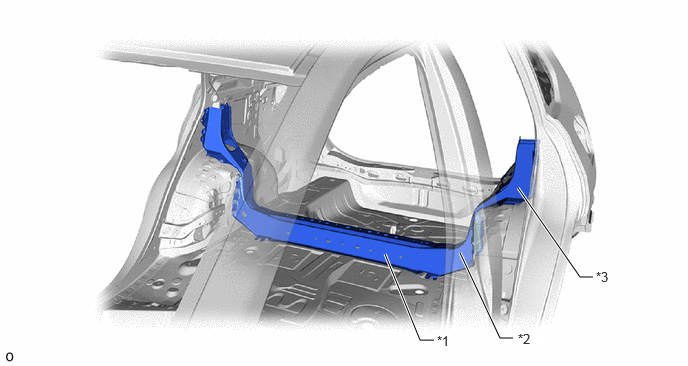
Ring Structure (This illustration is an example only.)
V123265C01
4.521,3.542 4.375,3.542 4.375,3.542 4.01,2.646 true 5.344,3.521 5.208,3.521 5.208,3.521 4.792,2.635 true 6.177,2.885 6.042,2.885 6.042,2.885 5.396,1.958 true 4.552,3.469 4.865,3.625 0.313,0.156 10 false *1 5.396,3.448 5.708,3.604 0.313,0.156 10 true *2 6.208,2.802 6.521,2.958 0.313,0.156 10 false *3
*1 Rear Floor Partition Panel Sub-assembly *2 Rear Absorber Reinforce Mounting Member
*3 Quarter Wheel House Gusset Inner - -


f.

High-rigidity foamed materials are used for the upper corners of the back door opening and the center of the sides*, increasing body rigidity.

HINT:

*: Models with High-rigidity Foamed Materials
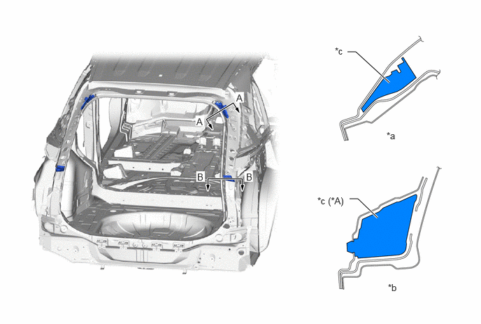

High-rigidity Foamed Materials (This illustration is an example only.)
V123254C02
5.177,0.771 5.302,0.771 5.302,0.771 5.802,1.229 true 5.208,2.958 5.333,2.958 5.333,2.958 5.625,3.24 true 3.521,1.375 3.677,1.573 0.156,0.198 10 false A 2.927,1.729 3.083,1.927 0.156,0.198 10 false A 2.938,2.552 3.094,2.75 0.156,0.198 10 false B 3.667,2.552 3.823,2.75 0.156,0.198 10 false B 5.76,1.938 5.969,2.135 0.208,0.198 10 false *a 5.781,4.198 5.99,4.396 0.208,0.198 10 false *b 4.99,0.677 5.188,0.833 0.198,0.156 10 false *c 4.729,2.906 5.208,3.073 0.479,0.167 10 false *c (*A)
*A Models with High-rigidity Foamed Materials - -
*a A - A Cross Section *b B - B Cross Section
*c High-rigidity Foamed Materials - -


g.

High-rigidity Urethane Sealant

i.

A high-rigidity urethane sealant is used to adhere the windshield glass and back window glass to the vehicle to improve body rigidity and ensure excellent driving stability.
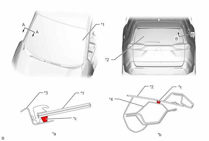
High-rigidity Urethane Sealant (This illustration is an example only.)
V123249C01
3.813,2.042 3.927,2.042 3.927,2.042 4.938,1.24 true 2.833,1.375 3.292,0.833 3.292,0.833 3.417,0.833 true 2.135,3.719 2.594,3.177 2.594,3.177 2.719,3.177 true 4.698,3.302 4.969,2.948 4.969,2.948 5.094,2.948 true 1.563,4.073 2.458,4.031 true 5.427,3.479 5.917,2.969 5.917,2.969 6.052,2.969 true 0.896,3.708 1.354,3.167 1.354,3.167 1.479,3.167 true 4.927,3.646 4.073,3.385 4.073,3.385 3.927,3.385 true 0.76,0.76 0.917,0.958 0.156,0.198 10 false A 1.229,1.01 1.385,1.208 0.156,0.198 10 false A 6.552,1.104 6.708,1.302 0.156,0.198 10 false B 6.01,1.24 6.167,1.438 0.156,0.198 10 false B 1.792,4.49 2.063,4.698 0.271,0.208 10 false *a 5.406,4.521 5.625,4.708 0.219,0.188 10 false *b 3.458,0.76 3.677,0.958 0.219,0.198 10 false *1 3.604,1.958 3.813,2.156 0.208,0.198 10 false *2 2.76,3.104 2.99,3.302 0.229,0.198 10 false *1 5.135,2.885 5.344,3.063 0.208,0.177 10 false *2 2.51,3.969 2.76,4.167 0.25,0.198 10 false *c 6.115,2.885 6.344,3.094 0.229,0.208 10 false *c 3.74,3.313 3.948,3.49 0.208,0.177 10 false *4 1.51,3.094 1.771,3.292 0.26,0.198 10 false *3
*1 Windshield Glass *2 Back Window Glass
*3 Front Body Side Outer Panel RH *4 Back Door Upper Panel Outside RH
*a A - A Cross Section *b B - B Cross Section
*c High-rigidity Urethane Sealant - -


h.

Structural Adhesive

·

Structural adhesive is used over a large range that includes the floor panel and the openings of the side and back doors, increasing panel connecting rigidity and ensuring superior driving stability.
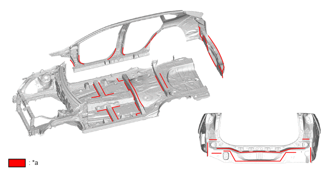
Structural Adhesive (This illustration is an example only.)
V123253C02
0.615,3.396 1.229,3.594 0.615,0.198 10 false : *a
*a Structural Adhesive - -