EG62 MANUAL TRANSMISSION / TRANSAXLE MANUAL TRANSAXLE SYSTEM CONTROL iMT SYSTEM
FUNCTION OF MAIN COMPONENTS
| Component | Function | |
|---|---|---|
| Fuel Injector Assembly | Injects fuel to the combustion chamber in accordance with ECM signals. | |
| Crank Position Sensor | Detects the engine speed and performs cylinder identification. | |
| Transmission Revolution Sensor | Detects the input speed of the transaxle. | |
| Clutch Pedal Stroke Sensor Assembly | Detects the amount of pedal effort applied to the clutch pedal. | |
| Accelerator Pedal Sensor Assembly | Detects the amount of pedal effort applied to the accelerator pedal. | |
| Speed Sensor | Detects the wheel speed. | |
| Integration Control & Panel Assembly | iMT Switch | Switches the iMT system on/off. |
| ECM | Controls the engine speed based on signals from each sensor and switch. | |
| Combination Meter Assembly | iMT Indicator | ·
Displays the iMT indicator (green) when the system is in the standby condition. ·
Displays the iMT indicator (amber) when there is a malfunction in the iMT system. |
| Multi-information Display | Displays the message when there is a malfunction in the system. | |
| Brake Actuator Assembly | Skid Control ECU | Transmits the wheel speed signal to the ECM. |
FUNCTION
Shift Synchronization Function
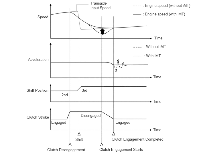
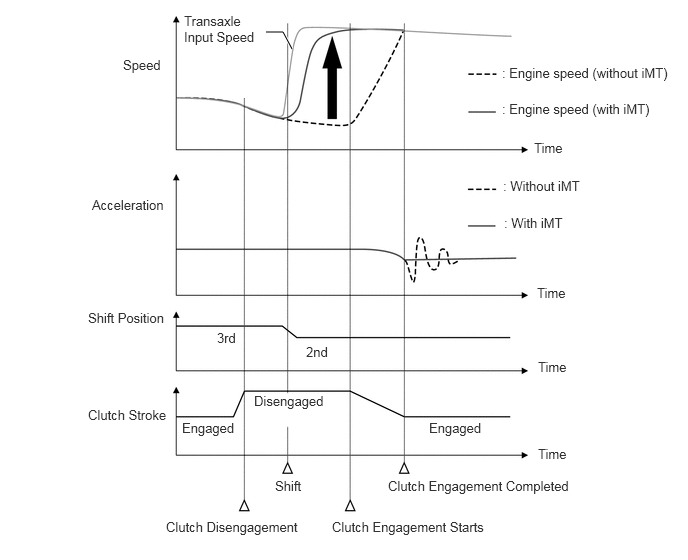
The iMT system detects shift changes from the driver (depressing the clutch pedal and operating the shift lever) and synchronizes the engine speed with the transaxle input speed after a shift change, achieving a smooth and comfortable shift feeling.
This system operates when the iMT switch is operated or the system is in SPORT mode and the iMT indicator (iMT system standby condition) is displayed on the combination meter assembly.
When Upshifting
- Control is performed so that the engine speed after a shift change does not drop below the transaxle input speed and to reduce the shock caused when the clutch is engaged, achieving a smooth shift feeling.
When Downshifting
- After a shift change, the engine speed is raised to synchronize with the transaxle input speed, reducing the shock caused when the clutch is engaged and achieving a smooth shift feeling.
DIAGNOSIS
When the ECM detects a malfunction, the ECM prohibits iMT system operation. In this case, in the combination meter displays the message.
The ECM will also store the Diagnostic Trouble Codes (DTCs) of the malfunctions. The DTCs stored in the ECM are output to the Global TechStream (GTS) via the DLC3.
For details, refer to the Repair Manual.