NM3620E
_52
Drivetrain
_076463
EG62 MANUAL TRANSMISSION / TRANSAXLE
_0377832
MANUAL TRANSAXLE SYSTEM
DE
DETAILS
F
EG62 MANUAL TRANSMISSION / TRANSAXLE MANUAL TRANSAXLE SYSTEM DETAILS GEAR TRAIN
CONSTRUCTION
a.
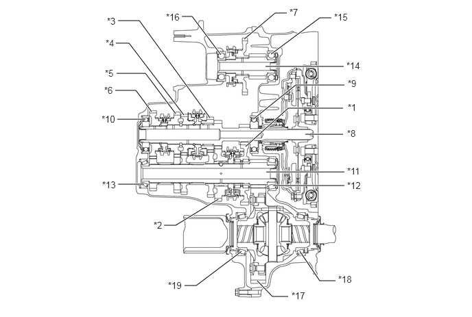
The arrangement of gears consists of 2 parallel shafts for the forward gears and a dedicated shaft for reverse gear with a constant mesh design being used.
b.
A helical gear is used for reverse, contributing to an improvement in quietness.
1.781,1.813 2.208,1.813
true
1.792,2.802 2.188,2.802
true
4.552,3.823 4.854,4.271
4.854,4.271 5.094,4.271
true
2.49,3.427 2.667,3.427
2.667,3.427 3.313,3.031
true
2.802,4.344 2.979,4.344
2.979,4.344 3.667,3.823
true
4.146,2.823 5.229,2.823
true
4.042,2.615 5.229,2.615
true
4.635,2.042 5.208,2.042
true
3.729,2.229 4.375,1.646
4.375,1.646 5.208,1.646
true
1.771,1.115 2.208,1.115
2.208,1.115 2.667,1.729
true
1.76,0.656 1.958,0.656
1.958,0.656 2.792,1.75
true
1.792,0.313 2.115,0.313
2.115,0.313 3.188,1.792
true
4.115,0.823 4.854,0.271
4.854,0.271 5.031,0.271
true
2.76,0.25 2.917,0.25
2.917,0.25 3.354,0.833
true
3.708,0.594 4.177,0.198
4.177,0.198 4.354,0.198
true
3.844,1.813 4.49,1.292
4.49,1.292 5.229,1.292
true
4.031,1.01 5.219,1.01
true
1.75,1.375 2.063,1.375
2.063,1.375 2.302,1.698
true
3.906,4.271 4.135,4.51
4.135,4.51 4.375,4.51
true
5.281,1.552 5.594,1.708
0.313,0.156
10
false
*1
2.333,3.344 2.646,3.5
0.313,0.156
10
false
*2
1.625,0.24 1.938,0.396
0.313,0.156
10
false
*3
1.604,0.573 1.917,0.729
0.313,0.156
10
false
*4
1.594,1.031 1.906,1.188
0.313,0.156
10
false
*5
1.583,1.292 1.896,1.448
0.313,0.156
10
false
*6
4.396,0.104 4.708,0.26
0.313,0.156
10
false
*7
5.271,1.948 5.583,2.104
0.313,0.156
10
false
*8
5.281,1.188 5.594,1.344
0.313,0.156
10
false
*9
1.542,1.729 2.01,1.885
0.469,0.156
10
false
*10
5.271,2.521 5.74,2.677
0.469,0.156
10
false
*11
5.271,2.74 5.74,2.896
0.469,0.156
10
false
*12
1.552,2.729 2.021,2.885
0.469,0.156
10
false
*13
5.26,0.917 5.729,1.073
0.469,0.156
10
false
*14
5.073,0.177 5.542,0.333
0.469,0.156
10
false
*15
2.521,0.177 2.99,0.333
0.469,0.156
10
false
*16
5.135,4.167 5.604,4.323
0.469,0.156
10
false
*18
2.552,4.26 3.021,4.417
0.469,0.156
10
false
*19
4.427,4.417 4.896,4.573
0.469,0.156
10
false
*17
| *1 | 1st Gear | *2 | 2nd Gear |
| *3 | 3rd Gear Sub-assembly | *4 | 4th Gear Sub-assembly |
| *5 | 5th Gear | *6 | 6th Gear |
| *7 | Reverse Gear | *8 | Input Shaft |
| *9 | Front Input Shaft Bearing | *10 | Rear Input Shaft Radial Ball Bearing |
| *11 | Output Shaft | *12 | Front Output Shaft Bearing |
| *13 | Rear Output Shaft Bearing | *14 | No. 2 Output Shaft |
| *15 | Front Reverse Gear Shaft Bearing | *16 | Rear Reverse Gear Shaft Bearing |
| *17 | Front Differential Ring Gear | *18 | Front Differential Case Front Tapered Roller Bearing |
| *19 | Front Differential Case Rear Tapered Roller Bearing | - | - |
c.
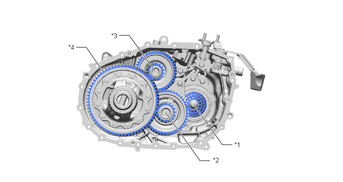
The output shaft and No. 2 output shaft are connected to the front differential ring gear at 2 different points. Torque is transmitted by the output shaft when a forward gear is engaged and is transmitted by the No. 2 output shaft when reverse gear is engaged.
4.042,2.188 4.646,3.031
4.646,3.031 4.854,3.031
true
3.458,2.354 4.177,3.365
4.177,3.365 4.385,3.365
true
2.49,0.74 2.698,0.74
2.698,0.74 3.24,1.49
true
1.594,0.99 1.802,0.99
1.802,0.99 2.156,1.51
true
4.896,2.948 5.208,3.104
0.313,0.156
10
false
*1
4.448,3.271 4.76,3.427
0.313,0.156
10
false
*2
2.323,0.667 2.635,0.823
0.313,0.156
10
false
*3
1.427,0.906 1.74,1.063
0.313,0.156
10
false
*4
| *1 | Input Shaft | *2 | Output Shaft |
| *3 | No. 2 Output Shaft | *4 | Front Differential Ring Gear |
OPERATION
a.
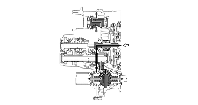
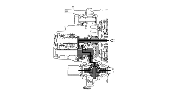
Gear Train Operation (1st)
b.
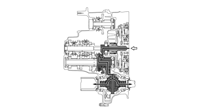
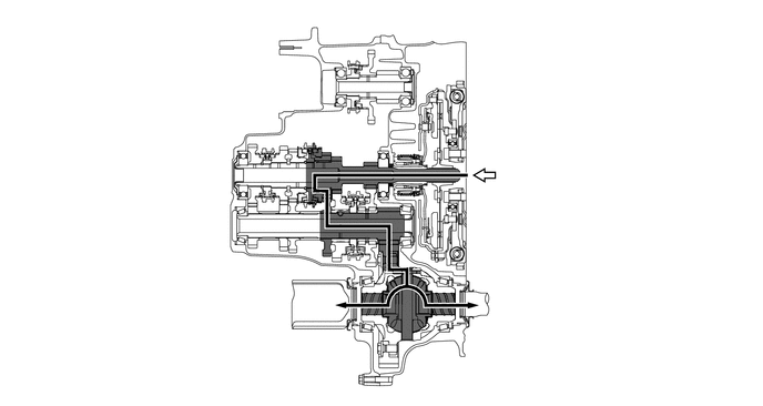
Gear Train Operation (2nd)
c.
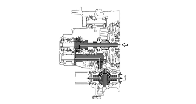
Gear Train Operation (3rd)
d.
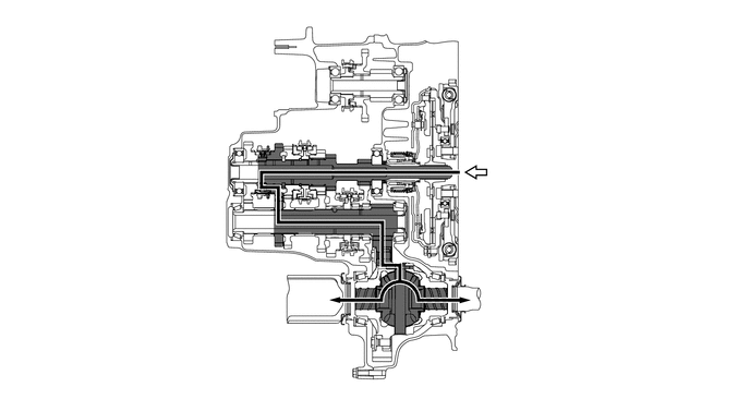
Gear Train Operation (4th)
e.
Gear Train Operation (5th)
f.
Gear Train Operation (6th)
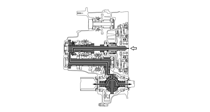
g.
Gear Train Operation (Reverse)