Home › Drivetrain › K120F (MULTIDRIVE / CVT) › CVT SYSTEM
NM3620E _52 Drivetrain _076477 K120F MULTIDRIVE / CVT _0378093 CVT SYSTEM DE DETAILS F

K120F MULTIDRIVE / CVT  CVT SYSTEM  DETAILS  GEAR TRAIN  


CONSTRUCTION


a.

Gear Type Power Transmission Mechanism

i.

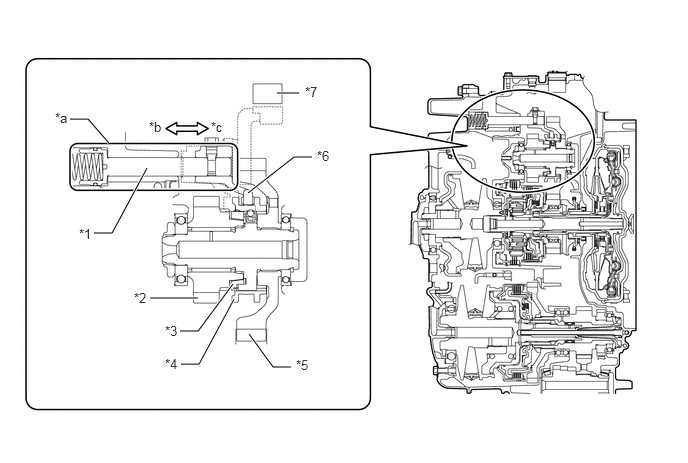
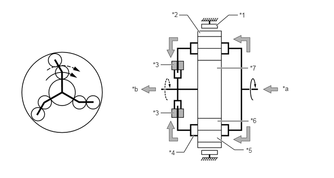
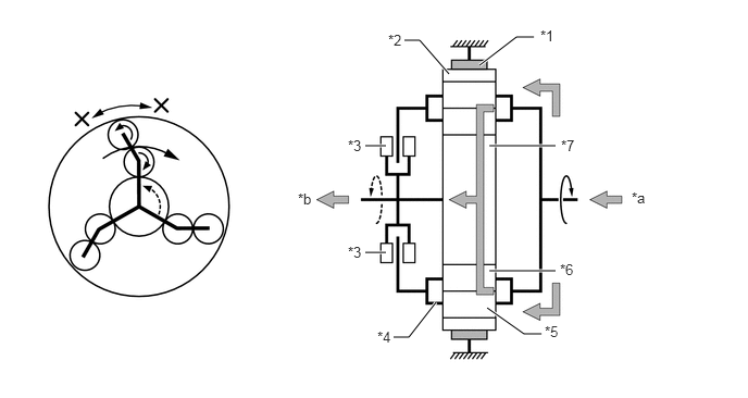
Gear type power transmission is used when the vehicle starts off, is being driven at low speeds or is reversing.


ii.

The synchronizer mechanism engages/disengages the No. 1 driven gear and No. 2 drive gear.


iii.

The pressure servo controls the shift fork shaft and synchronizer mechanism by controlling the oil pressure.


iv.

By using efficient gear type power transmission, direct and smooth start-off has been achieved.


v.

When using the belt type power transmission mechanism, the gear type power transmission mechanism is disconnected by the synchronizer mechanism to reduce gear losses.


vi.

Engagement and release of the synchronizer mechanism is automatically controlled by using the stroke sensor to detect the position of the shift fork shaft, and by using the linear solenoid valve SLG of the servo mechanism to directly control the shift fork shaft.
X140708C01
2.885,0.969 3.115,0.969 true 0.979,2.427 1.167,2.427 1.167,2.427 1.531,1.75 true 1.875,3.448 2.063,3.448 2.063,3.448 2.427,2.958 true 1.885,3.792 2.073,3.792 2.073,3.792 2.438,3.115 true 2.583,2.01 3.063,1.635 3.063,1.635 3.25,1.635 true 0.729,1.24 0.917,1.24 0.917,1.24 1.135,1.49 true 1.563,3.104 2.063,3.104 true 2.594,3.479 2.844,3.823 2.844,3.823 3.031,3.823 true 0.823,2.354 1.135,2.51 0.313,0.156 10 false *1 1.719,3.365 2.031,3.521 0.313,0.156 10 false *3 1.719,3.708 2.031,3.865 0.313,0.156 10 false *4 3.302,1.542 3.615,1.698 0.313,0.156 10 false *6 3.177,0.875 3.49,1.031 0.313,0.156 10 false *7 0.573,1.146 0.885,1.302 0.313,0.156 10 false *a 1.552,1.24 1.865,1.396 0.313,0.156 10 false *b 2.198,1.24 2.51,1.396 0.313,0.156 10 false *c 1.396,3.021 1.708,3.177 0.313,0.156 10 false *2 3.083,3.719 3.396,3.875 0.313,0.156 10 false *5
*1 Shift Fork Shaft *2 No. 2 Drive Gear
*3 Synchronizer Ring *4 Hub Sleeve
*5 No. 1 Driven Gear *6 Shift Fork
*7 Clutch Stroke Sensor - -
*a Servo Mechanism *b Engaged (Synchronizer Mechanism)
*c Disengaged (Synchronizer Mechanism) - -


b.

Belt Type Power Transmission Mechanism

i.

The belt transmission mechanism is used other than when the vehicle starts off, is being driven at low speeds or is reversing.


ii.

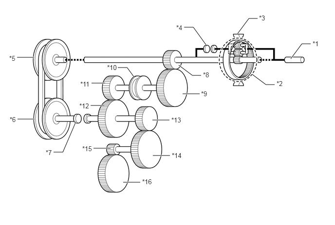
The belt transmission mechanism consists of a continuously variable transmission mechanism with a steel belt and a pair of pulleys. The groove width of the pulley changes according to the oil pressure to change the diameter of the steel belt, changing the pulley ratio.


c.

Forward/Rearward and Gear/Belt Switching Mechanism

i.

The double pinion planetary gear, C1 clutch and B1 brake are situated at the input side of the belt type power transmission mechanism and the C2 clutch is situated at the output side and are used to switch between belt/gear power transmission and forward/reverse.
X140920C01
0.365,1.229 0.729,1.229 true 0.375,2.552 0.74,2.552 true 2.635,3.906 3,3.906 true 3.271,3.333 3.635,3.333 true 3.26,2.573 3.625,2.573 true 3.823,1.396 4.115,1.615 4.115,1.615 4.302,1.615 true 6.219,1.26 6.458,0.938 6.458,0.938 6.646,0.938 true 5.083,0.719 5.323,0.396 5.323,0.396 5.51,0.396 true 3.938,0.583 4.135,0.583 4.135,0.583 4.406,0.958 true 1.146,3.26 1.344,3.26 1.344,3.26 1.625,2.604 true 2.521,1.448 2.719,1.448 2.719,1.448 2.865,1.646 true 3.906,2.01 4.271,2.01 true 1.958,1.781 2.25,1.781 true 2,3.177 2.365,3.177 true 1.938,2.26 2.229,2.26 true 5.396,1.594 5.688,1.813 5.688,1.813 5.875,1.813 true 0.198,1.167 0.51,1.323 0.313,0.156 10 false *5 0.208,2.479 0.521,2.635 0.313,0.156 10 false *6 0.979,3.188 1.292,3.344 0.313,0.156 10 false *7 1.76,3.104 2.073,3.26 0.313,0.156 10 false *15 3.042,3.813 3.354,3.969 0.313,0.156 10 false *16 3.677,3.25 3.99,3.406 0.313,0.156 10 false *14 3.667,2.49 3.979,2.646 0.313,0.156 10 false *13 4.302,1.927 4.615,2.083 0.313,0.156 10 false *9 4.344,1.521 4.656,1.677 0.313,0.156 10 false *8 6.688,0.854 7,1.01 0.313,0.156 10 false *1 2.292,1.365 2.677,1.552 0.385,0.188 10 false *10 1.719,1.719 2.031,1.875 0.313,0.156 10 false *11 1.698,2.188 2.01,2.354 0.313,0.167 10 false *12 5.542,0.302 5.854,0.458 0.313,0.156 10 false *3 3.771,0.51 4.083,0.667 0.313,0.156 10 false *4 5.917,1.708 6.229,1.865 0.313,0.156 10 false *2
*1 Input Shaft *2 Planetary Gear Unit
*3 B1 Brake *4 C1 Clutch
*5 Primary Pulley *6 Secondary Pulley
*7 C2 Clutch *8 No. 1 Drive Gear
*9 No. 1 Driven Gear *10 Synchronizer Mechanism
*11 No. 2 Drive Gear *12 No. 2 Driven Gear
*13 Reduction Drive Gear *14 Reduction Driven Gear
*15 Differential Drive Pinion *16 Differential Ring Gear


ii.

Gear/Belt Switching Mechanism

1.

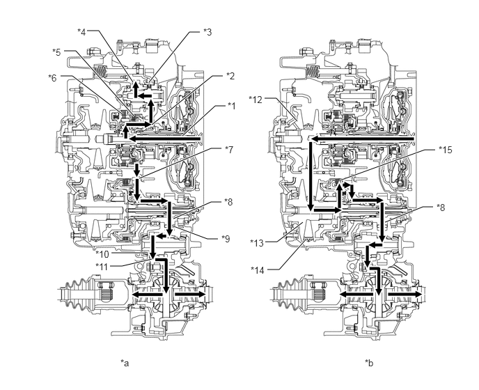
By engaging/disengaging the C1 clutch and C2 clutch, the transmission is switched between belt type power transmission and gear type power transmission.

2.

Smooth switching is achieved by using the linear solenoid valve SL1 and linear solenoid valve SL2 to accurately and responsively control the oil pressure of each clutch.

Torque Flow
X140707C01
2.729,2.031 3.219,1.583 3.219,1.583 3.375,1.583 true 2.271,1.865 3.177,1.135 3.177,1.135 3.333,1.135 true 2.229,1.229 2.833,0.479 2.833,0.479 2.99,0.479 true 1.302,0.458 1.479,0.458 1.479,0.458 1.99,1.229 true 0.958,0.76 1.135,0.76 1.135,0.76 2.01,1.74 true 0.906,1.135 1.083,1.135 1.083,1.135 1.833,1.708 true 2.083,2.667 3.156,2.219 3.156,2.219 3.313,2.219 true 2.594,3.271 3.156,3.021 3.156,3.021 3.313,3.021 true 2.573,3.375 3.104,3.573 3.104,3.573 3.26,3.573 true 1.646,3.979 1.823,3.979 1.823,3.979 2.271,3.875 true 1.667,3.781 2.198,3.781 true 3.958,1.469 4.135,1.469 4.135,1.469 4.448,1.813 true 3.969,3.615 4.146,3.615 4.146,3.615 4.531,3.323 true 4,4.031 4.177,4.031 4.177,4.031 4.583,3.573 true 5.083,2.698 6.354,2.24 6.354,2.24 6.51,2.24 true 5.76,3.323 6.323,3.094 6.323,3.094 6.479,3.094 true 3.406,1.5 3.719,1.656 0.313,0.156 10 false *1 3.385,1.052 3.698,1.208 0.313,0.156 10 false *2 3.042,0.396 3.354,0.552 0.313,0.156 10 false *3 1.156,0.396 1.469,0.552 0.313,0.156 10 false *4 0.781,0.698 1.094,0.854 0.313,0.156 10 false *5 0.719,1.083 1.031,1.24 0.313,0.156 10 false *6 3.365,2.156 3.677,2.313 0.313,0.156 10 false *7 3.354,2.938 3.667,3.094 0.313,0.156 10 false *8 3.313,3.49 3.625,3.646 0.313,0.156 10 false *9 1.427,3.719 1.896,3.875 0.469,0.156 10 false *10 1.427,3.906 1.896,4.063 0.469,0.156 10 false *11 3.719,1.406 4.188,1.563 0.469,0.156 10 false *12 3.74,3.552 4.208,3.708 0.469,0.156 10 false *13 3.75,3.958 4.219,4.115 0.469,0.156 10 false *14 6.563,2.156 7.031,2.313 0.469,0.156 10 false *15 1.802,5.344 2.115,5.5 0.313,0.156 10 false *a 5.458,5.344 5.771,5.5 0.313,0.156 10 false *b 6.531,3.021 6.844,3.177 0.313,0.156 10 false *8
*1 Input Shaft *2 No. 1 Drive Gear
*3 Synchromesh *4 No. 2 Drive Gear
*5 C1 Clutch *6 B1 Brake
*7 No. 2 Driven Gear *8 Reduction Drive Gear
*9 Reduction Driven Gear *10 Differential Drive Pinion
*11 Differential Ring Gear *12 Primary Pulley
*13 Secondary Pulley *14 Steel Belt
*15 C2 Clutch - -
*a Gear Type Power Transmission *b Belt Type Power Transmission


iii.

Forward/Reverse Switching Unit

1.

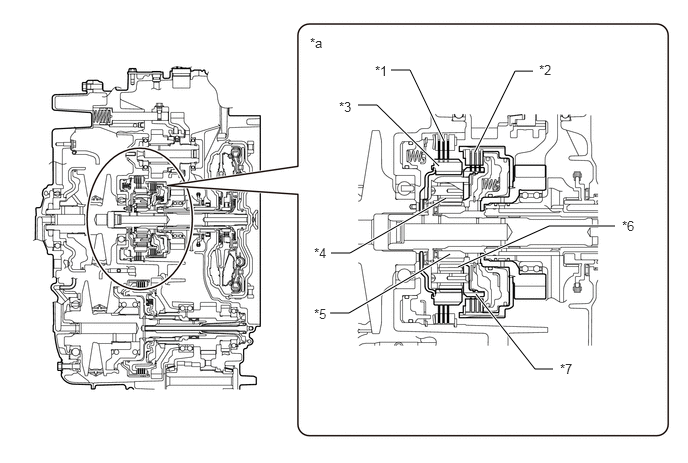
The forward/reverse switching unit consists of a planetary gear, a C1 clutch and a B1 brake.

2.

Smooth switching is achieved by using the linear solenoid valve SL1 and linear solenoid valve SLG to accurately and responsively control the oil pressure of clutch and brake.

3.

The C1 clutch, which operates during a forward movement, connects the input shaft with the planetary carrier.

4.

The B1 brake, which operates during reverse movement, keeps the ring gear stationary.
X140709C01
4.073,0.729 4.271,0.729 4.271,0.729 4.625,1.469 true 4.948,1.583 5.365,0.74 5.365,0.74 5.552,0.74 true 3.729,1.094 3.927,1.094 3.927,1.094 4.573,1.729 true 3.448,2.635 3.646,2.635 3.646,2.635 4.646,2.063 true 3.438,3.26 3.635,3.26 3.635,3.26 4.688,2.646 true 4.771,2.781 5.719,2.354 5.719,2.354 6.406,2.354 true 4.958,3.063 5.573,3.844 5.573,3.844 5.76,3.844 true 3.906,0.656 4.188,0.854 0.281,0.198 10 false *1 5.615,0.646 5.938,0.896 0.323,0.25 10 false *2 3.531,1.031 3.844,1.188 0.313,0.156 10 false *3 3.271,2.552 3.583,2.708 0.313,0.156 10 false *4 3.271,3.188 3.583,3.344 0.313,0.156 10 false *5 6.479,2.271 6.792,2.427 0.313,0.156 10 false *6 5.833,3.76 6.146,3.917 0.313,0.156 10 false *7 3.229,0.365 3.542,0.521 0.313,0.156 10 false *a
*1 B1 Brake *2 C1 Clutch
*3 Ring Gear *4 No. 1 Pinion
*5 Sun Gear *6 No. 2 Pinion
*7 Planetary Carrier - -
*a Forward/Reverse Switching Unit - -


OPERATION


a.

Forward/Reverse Driving

i.

Forward Driving

1.

The C1 clutch is connected when advancing, and engine torque is input from the input shaft to the planetary carrier and is output to the sun gear.
X140918C01
4.656,1.458 5.323,1.458 true 4.667,2.594 5.333,2.594 true 3.448,1.385 3.729,1.385 true 3.448,2.417 3.729,2.417 true 4.635,0.552 4.906,0.323 4.906,0.323 5.104,0.323 true 4.656,2.948 5.031,3.208 5.031,3.208 5.229,3.208 true 3.844,0.323 4.021,0.323 4.021,0.323 4.292,0.708 true 4.156,2.906 3.948,3.26 3.948,3.26 3.781,3.26 true 5.135,0.24 5.448,0.396 0.313,0.156 10 false *1 3.688,0.229 4,0.385 0.313,0.156 10 false *2 3.281,1.302 3.594,1.458 0.313,0.156 10 false *3 3.625,3.188 3.938,3.344 0.313,0.156 10 false *4 5.281,3.135 5.594,3.292 0.313,0.156 10 false *5 5.365,1.375 5.677,1.531 0.313,0.156 10 false *7 6.063,1.813 6.375,1.969 0.313,0.156 10 false *a 2.833,1.823 3.146,1.979 0.313,0.156 10 false *b 3.281,2.333 3.594,2.49 0.313,0.156 10 false *3 5.375,2.5 5.688,2.656 0.313,0.156 10 false *6
*1 B1 Brake (Off) *2 Ring Gear
*3 C1 Clutch (On) *4 Planetary Carrier
*5 No. 2 Pinion *6 No. 1 Pinion
*7 Sun Gear - -
*a Input *b Output


ii.

Reverse Driving

1.

Engine torque is input to the planetary carrier when reversing. The ring gear is fixed by the B1 brake to transmit engine torque to the sun gear with inverse rotation.
X140919C01
4.688,2.594 5.323,2.594 true 4.688,1.396 5.323,1.396 true 4.667,2.948 5.021,3.198 5.021,3.198 5.188,3.198 true 3.5,2.417 3.698,2.417 true 3.5,1.396 3.698,1.396 true 4.594,0.625 4.948,0.354 4.948,0.354 5.115,0.354 true 3.875,0.385 4.021,0.385 4.021,0.385 4.302,0.708 true 3.771,3.229 3.917,3.229 3.917,3.229 4.177,2.896 true 5.177,0.26 5.49,0.417 0.313,0.156 10 false *1 3.719,0.302 4.031,0.458 0.313,0.156 10 false *2 3.333,1.313 3.646,1.469 0.313,0.156 10 false *3 3.615,3.146 3.927,3.302 0.313,0.156 10 false *4 5.219,3.094 5.531,3.25 0.313,0.156 10 false *5 5.365,2.5 5.677,2.656 0.313,0.156 10 false *6 5.375,1.313 5.688,1.469 0.313,0.156 10 false *7 6.052,1.813 6.365,1.969 0.313,0.156 10 false *a 2.854,1.823 3.167,1.979 0.313,0.156 10 false *b 3.333,2.333 3.646,2.49 0.313,0.156 10 false *3
*1 B1 Brake (On) *2 Ring Gear
*3 C1 Clutch (Off) *4 Planetary Carrier
*5 No. 2 Pinion *6 No. 1 Pinion
*7 Sun Gear - -
*a Input *b Output


iii.

Power is transmitted from the sun gear via the No. 1 drive gear to the gear type power transmission mechanism, and then from the gear type power transmission mechanism to the reduction drive gear mechanism via the No. 2 driven gear.


b.

Belt Type Power Transmission

i.

By disengaging both the C1 clutch and B1 brake, the planetary gear is disengaged and engine torque is transmitted to the belt type power transmission mechanism.


ii.

Power is transmitted from the primary pulley to the secondary pulley via the belt, and then to the reduction drive gear mechanism via the C2 clutch.