FRONT SUSPENSION FRONT SUSPENSION SYSTEM DETAILS STABILIZER BAR
CONSTRUCTION
A high rigidity and lightweight hollow stabilizer bar is used. The installation position is optimized, improving roll rigidity. As a result, rolling is suppressed during turning, achieving a stable turning posture.
A ball joint is used at both ends of the front stabilizer link assembly.
The front No. 1 stabilizer bar bush reduces twisting torque by using a fluorine coating in the bore diameter. As a result, the suspension moves easily when receiving input from the road surface. The rubber and resin seat portions are split, making it possible to use a cylindrical shape for the rubber portions and reducing the difference in the spring constant in the bound and rebound directions. As a result, an excellent roll feeling is achieved. Furthermore, the surfaces that contact the bracket are given a barrel shape, suppressing opening of the rubber portions caused by input received from the road surface, and preventing mud, sand and other materials from entering between the front stabilizer bar and front stabilizer bush.
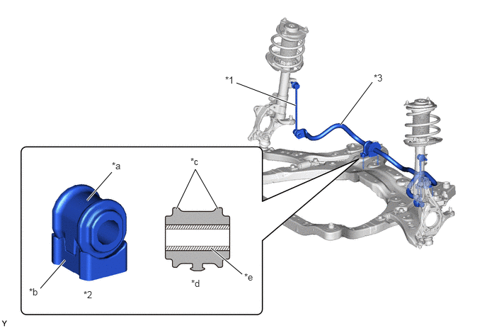
| *1 | Front Stabilizer Link Assembly | *2 | Front No. 1 Stabilizer Bar Bush |
| *3 | Front Stabilizer Bar | - | - |
| *a | Rubber Portion | *b | Resin Seat Portion |
| *c | Barrel Shape | *d | Cross Section |
| *e | Fluorine Coating | - | - |