Home › Engine / Hybrid System › HYBRID / BATTERY CONTROL › HYBRID BATTERY SYSTEM (for LITHIUM-ION BATTERY) › from 2020.05
NM3620E _51 Engine / Hybrid System _076668 HYBRID / BATTERY CONTROL _0430218 HYBRID BATTERY SYSTEM(for LITHIUM-ION BATTERY) CO CONTROL F

HYBRID / BATTERY CONTROL  HYBRID BATTERY SYSTEM(for LITHIUM-ION BATTERY)  CONTROL  HYBRID VEHICLE CONTROL ECU  


SYSTEM CONTROL


a.

State Of Charge (SOC)

i.

In order to maintain the SOC at the appropriate level all the time, the hybrid vehicle control ECU controls the hybrid system optimally.
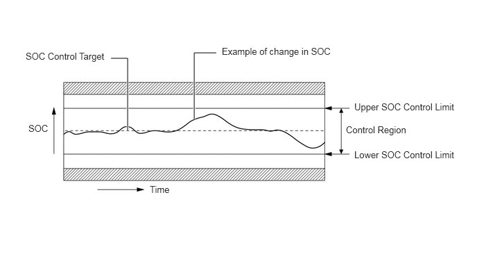
W101107E07
1.917,1.958 1.917,0.875 1.917,0.875 1.667,0.875 true 2.917,1.792 2.917,0.792 2.917,0.792 3.25,0.792 true 0.385,0.76 1.688,1.073 1.302,0.313 10 SOC Control Target 3.333,0.688 5.125,1.021 1.792,0.333 10 Example of change in SOC 0.427,1.844 0.833,2.208 0.406,0.365 10 SOC 2.25,2.76 2.729,3.073 0.479,0.313 10 Time 5.323,1.521 6.927,1.865 1.604,0.344 10 Upper SOC Control Limit 5.198,1.865 6.333,2.219 1.135,0.354 10 Control Region 5.323,2.24 6.917,2.656 1.594,0.417 10 Lower SOC Control Limit


b.

Detection of Insulation Resistance Decrease

i.

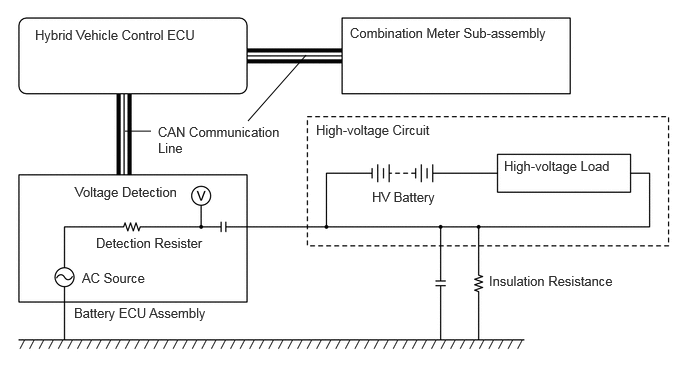
The leak detection circuit is built into the battery ECU assembly. The leak detection circuit constantly monitors that the insulation resistance between high-voltage circuits and body ground is maintained.


ii.

The hybrid vehicle control ECU determines decreases in the insulation resistance based on the information from the battery ECU assembly.


iii.

The leak detection circuit has an AC source and causes a small amount of AC to flow to the high-voltage circuit (positive and negative).


iv.

The more insulation resistance decreases, the more voltage steps down at the detection resistor and the lower the waves of AC. The insulation resistance value is detected based on the amplitude of AC waves.
W132257E09
2.583,1.26 3.188,0.573 false 1.302,1.365 1.573,1.365 false 0.365,0.281 2.365,0.719 2,0.438 10 false Hybrid Vehicle Control ECU 1.646,1.292 2.958,1.719 1.313,0.427 10 false CAN Communication Line 3.646,0.26 5.813,0.844 2.167,0.583 10 false Combination Meter Sub-assembly 3.292,1.271 4.99,1.604 1.698,0.333 10 false High-voltage Circuit 5.25,1.646 6.531,1.979 1.281,0.333 10 false High-voltage Load 3.875,1.969 4.979,2.313 1.104,0.344 10 false HV Battery 0.781,1.917 1.927,2.271 1.146,0.354 10 false Voltage Detection 1,2.448 2.438,2.75 1.438,0.302 10 false Detection Resister 0.854,2.813 2.094,3.115 1.24,0.302 10 false AC Source 0.771,3.177 3.781,3.51 3.01,0.333 10 false Battery ECU Assembly 5.094,2.844 6.813,3.219 1.719,0.375 10 false Insulation Resistance


c.

Cut-off of High-Voltage Circuits during Collision

i.

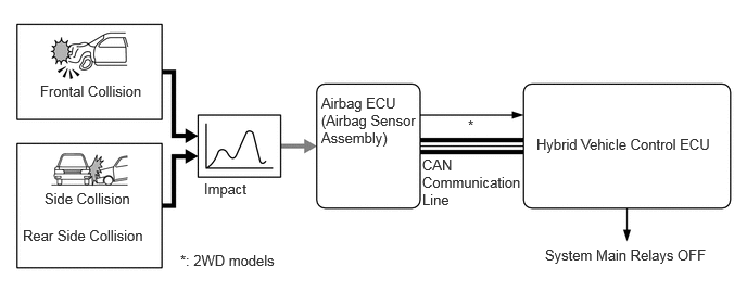
If the vehicle is involved in a collision as described below, the hybrid vehicle control ECU will shut down the power supply by turning the system main relays off for safety.


ii.

The hybrid vehicle control ECU receives the airbag deployment signal from the airbag ECU assembly during a frontal collision, side collision or rear collision.
W132097E16
0.385,0.792 1.479,1.094 1.094,0.302 10 false Frontal Collision 0.427,1.823 1.438,2.167 1.01,0.344 10 false Side Collision 0.219,2.177 1.542,2.531 1.323,0.354 10 false Rear Side Collision 1.958,1.729 2.875,1.927 0.917,0.198 10 false Impact 3.083,0.906 3.99,1.594 0.906,0.688 10 false Airbag ECU (Airbag Sensor Assembly) 5.146,1.302 6.896,1.833 1.75,0.531 10 false Hybrid Vehicle Control ECU 4.052,1.5 5,2.052 0.948,0.552 10 false CAN Communication Line 5.229,2.365 6.906,2.583 1.677,0.219 10 false System Main Relays OFF 4.49,1.125 4.646,1.323 0.156,0.198 10 false * 1.729,2.417 2.781,2.74 1.052,0.323 10 false *: 2WD models