EXTERIOR PANELS / TRIM BODY STRUCTURE DETAILS SAFETY FEATURES
FUNCTION
Impact Absorbing Structure for Frontal Collision
In order to ensure passenger protection performance during frontal collisions, a vehicle structure that optimally absorbs and disperses the impact load has been developed.
Impact load from the upper member (*1 in illustration) is dissipated to the roof rail (*3 in illustration) through the front body pillar (*2 in illustration) during frontal collisions (*A in illustration).
Impact load from the side member (*4 in illustration) is dispersed to the rocker (*6 in illustration) through the dash cross member (*5 in illustration) during frontal collisions (*A in illustration).
Impact load from the front bumper reinforcement (*7 in illustration) is dispersed to the suspension member (*8 in illustration) through the No. 2 member (*9 in illustration) during frontal collisions (*A in illustration).
Impact from the side member (*4 in illustration) is efficiently dispersed to the rocker (*6 in illustration), kick upper (*10 in illustration) and tunnel parts (*11 in illustration) through the dash cross member (*5 in illustration) during offset collisions (*B in illustration).
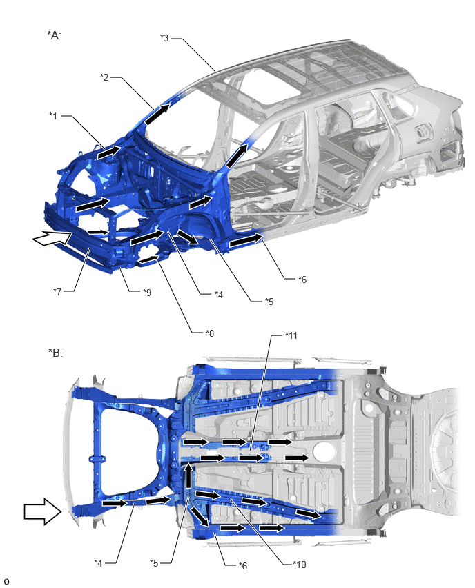
| *A | Frontal Collision (Full-lap) | *B | Frontal Collision (Offset) |
| *1 | Upper Member | *2 | Front Body Pillar |
| *3 | Roof Rail | *4 | Side Member |
| *5 | Dash Cross Member | *6 | Rocker |
| *7 | Front Bumper Reinforcement | *8 | Suspension Member |
| *9 | No. 2 Member | *10 | Kick Upper |
| *11 | Tunnel Parts | - | - |

|
Front Impact Energy | 
|
Dissipate |
A widened structure is used for the side member. As a result, high collision safety is ensured for various types of collisions.
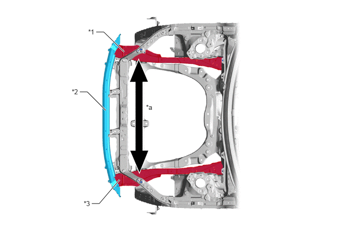
| *1 | Front Side Member RH | *2 | Front Bumper Reinforcement |
| *3 | Front Side Member LH | - | - |
| *a | Wider | - | - |
A No. 2 member is provided under the front bumper reinforcement and side member. As a result, the amount of impact load absorbed during the initial stage of the collision is increased, improving collision energy absorption efficiency.
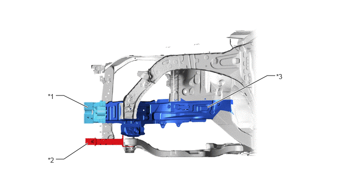
| *1 | Front Bumper Reinforcement | *2 | No. 2 Member |
| *3 | Front Side Member LH | - | - |
Roof Crush Resistance
Hot-stamped steel (tensile strength: 1500 MPa class), ultra high-tensile strength steel (tensile strength: 1180 MPa and 980 MPa class) and high-tensile strength steel (tensile strength: 780 MPa and 590 MPa class) are used in the body frame, achieving weight reduction and structure simplification while ensuring strength.
Impact load from the top of the vehicle is supported by the front body pillar (*1 in illustration), center body pillar (*2 in illustration), front header (*3 in illustration), roof center reinforcement (*4 in illustration) and rail outer (*5 in illustration), suppressing cabin deformation.
The wall of the center body pillar inner (*6 in illustration) wraps around the upper part of the rocker (*7 in illustration). As a result, collapsing of the rail is suppressed when impact load is applied to it from the top of the vehicle.
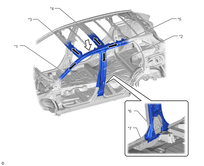
| *1 | Front Body Pillar (Tensile Strength: 1500 MPa Class) | *2 | Center Body Pillar (Tensile Strength: 1500 MPa Class) |
| *3 | Front Header (Tensile Strength: 980 MPa Class) | *4 | Roof Center Reinforcement (Tensile Strength: 1180 MPa Class) |
| *5 | Rail Outer (Tensile Strength: 1180 and 590 MPa Class) | *6 | No. 4 Inner Pillar Sub-assembly LH (Tensile Strength: 590 MPa Class) |
| *7 | Floor Side Member Inner LH (Tensile Strength: 1180 MPa Class) | - | - |
|
|
Above Impact Energy |
|
Dissipate |
The roof side rail upper (*1 in illustration) and roof side rail outer No. 2 (*2 in illustration) are positioned so that they extend to the front of the quarter body pillar. As a result, collapsing of the rail is suppressed when impact load is applied to it from the top of the vehicle.
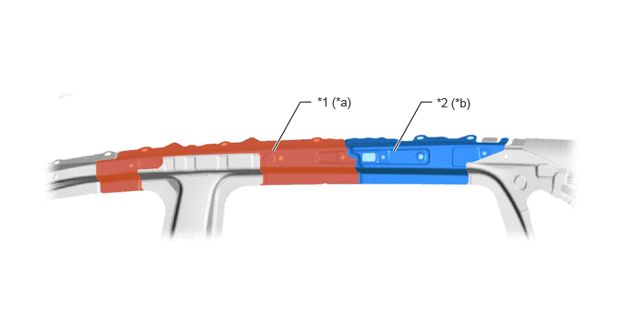
| *1 | Roof Side Rail Upper LH | *2 | Roof Side Rail Outer No. 2 LH |
| *a | Ultra High-tensile Strength Steel (Tensile Strength: 1180 MPa Class) | *b | High-tensile Strength Steel (Tensile Strength: 590 MPa Class) |
Impact Absorbing Structure for Side Collision
Hot-stamped steel (tensile strength: 1500 MPa class), ultra high-tensile strength steel (tensile strength: 1180 MPa and 980 MPa class) and high-tensile strength steel (tensile strength: 780 MPa and 590 MPa and 440 MPa class) are used in the body frame, achieving weight reduction and structure simplification while ensuring strength.
Hot-stamped sheet steel, ultra high strength sheet steel and high strength sheet steel is used for the body frameworks, increasing strength and suppressing cabin deformation.
Impact load from the center body pillar (*1 in illustration) is dispersed to the rocker (*3 in illustration) through the center body pillar reinforcement lower (*2 in illustration) during side collisions.
Impact load from the center body pillar (*1 in illustration) is dispersed to the roof center reinforcement (*4 in illustration) through the rail outer (*5 in illustration) during side collisions.
Impact load from the center body pillar (*1 in illustration) is dispersed to the front header (*6 in illustration) and cowl top panel (*7 in illustration) through the front body pillar (*8 in illustration) during side collisions.
A high strength and thick front door impact beam (*9 in illustration) with a large diameter is used, suppressing inwards intrusion during collisions with another vehicle.
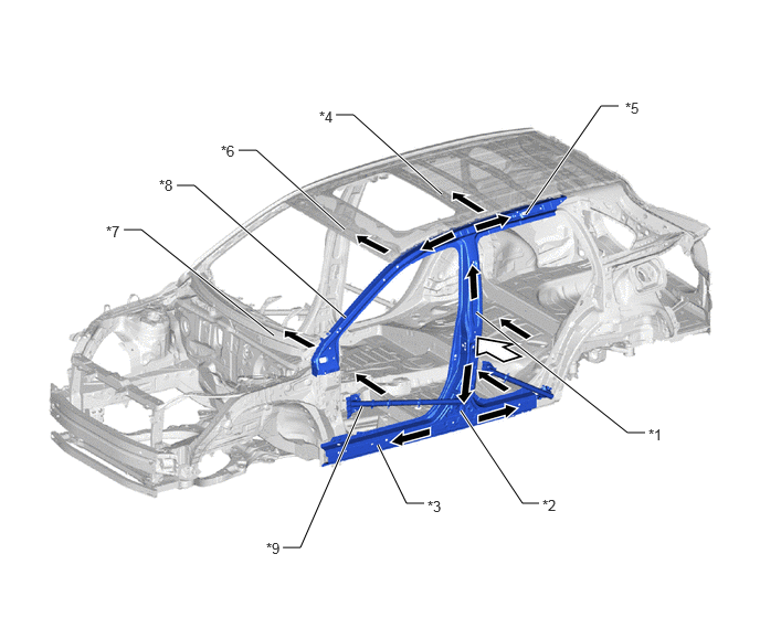
| *1 | Center Body Pillar (Tensile Strength: 1500 MPa Class) | *2 | Center Body Pillar Reinforcement Lower (Tensile Strength: 440 MPa Class) |
| *3 | Rocker (Tensile Strength: 1180 MPa Class) | *4 | Roof Center Reinforcement (Tensile Strength: 1180 MPa Class) |
| *5 | Rail Outer (Tensile Strength: 1180 and 590 MPa Class) | *6 | Front Header (Tensile Strength: 980 MPa Class) |
| *7 | Cowl Top Panel | *8 | Front Body Pillar (Tensile Strength: 1500 MPa Class) |
| *9 | Front Door Impact Beam | - | - |
|
|
Side Impact Energy |
|
Dissipate |
Diagonal reinforcements are used for the rear door. As a result, door deformation is suppressed during collisions, helping ensure that the doors can be opened.
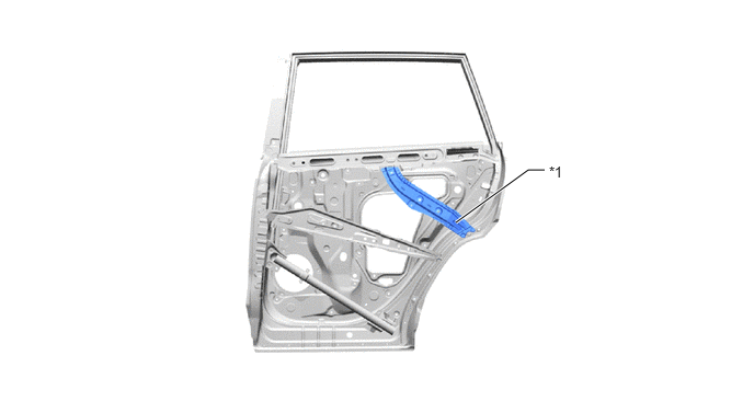
| *1 | Rear Door Rear Upper Frame Reinforcement LH | - | - |
Bulkheads are used inside the rocker to create a structure that efficiently transmits impact load to the floor cross reinforcement during side collisions.
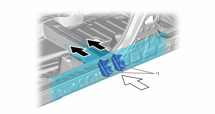
| *1 | Rocker Panel Reinforcement No. 4 LH | - | - |
|
|
Dissipate |
|
Side Impact Energy |
For the normal roof specification, the ultra high strength sheet steel (tensile strength: 1180 MPa class) roof center reinforcement (*1 in illustration) and roof rail (*2 in illustration) are connected by spot welds to create a structure that transmits and disperses impact load from the center body pillar to the roof during collisions.
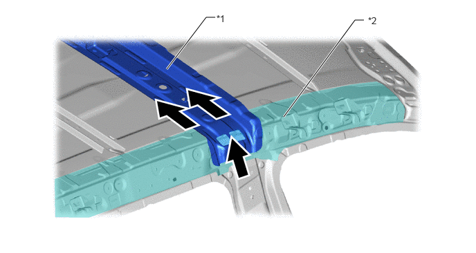
| *1 | Roof Center Reinforcement | *2 | Roof Rail |
|
|
Dissipate | - | - |
For the sliding roof specification, the sliding roof unit reinforcement (*1 in illustration) and roof rail (*2 in illustration) are connected through the curtain shield airbag inflator bracket (*3 in illustration). As a result, a structure is created that efficiently transmits and disperses impact load from the center body pillar to the roof during collisions.
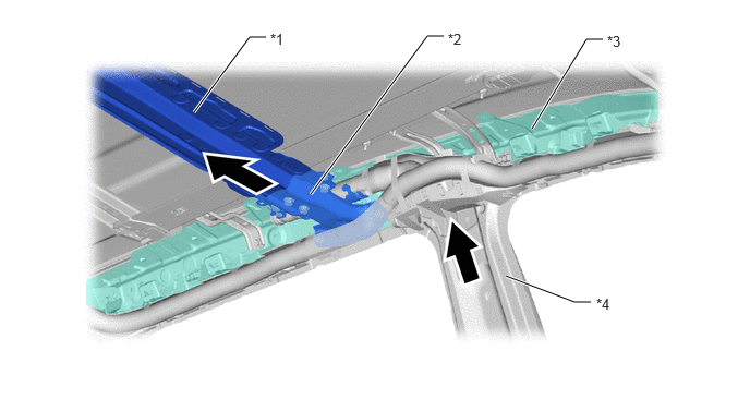
| *A | Destination package for Korea | - | - |
| *1 | Roof Center Reinforcement | *2 | Roof Rail |
| *3 | Curtain Shield Airbag Inflator Bracket | - | - |
|
|
Dissipate | - | - |
Impact Absorbing Structure for Rear Collision
A light and high strength rear bumper reinforcement sub-assembly is used. It uses ultra high strength sheet steel.
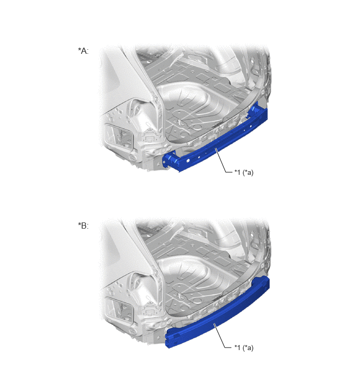
| *A | Models for Europe | *B | Except models for Europe |
| *1 | Rear Bumper Reinforcement | - | - |
| *a | Ultra High-tensile Strength Steel (Tensile Strength: 980 MPa Class) | - | - |
A rear bumper reinforcement that uses ultra high strength sheet steel is provided to achieve high support strength when an impact is received from the rear.
A high strength rear bumper reinforcement is used to disperse impact energy to the opposite side of the vehicle during rear collisions, suppressing cabin deformation.
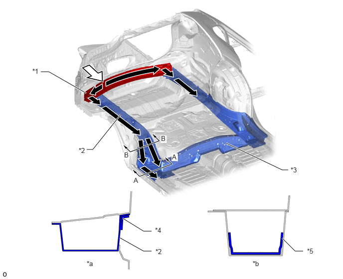
| *1 | Rear Bumper Reinforcement | *2 | Rear Floor Side Member RH |
| *3 | Rear Floor Cross Member Center | *4 | Rear Rocker Reinforcement RH |
| *5 | Rear Floor Side Member Reinforcement | - | - |
| *a | A - A Cross Section | *b | B - B Cross Section |
|
|
Rear Impact Energy |
|
Dissipate |
Reduction of Pedestrian Leg Injury
A front bumper energy absorber No. 2 is provided in front of the front bumper reinforcement and a front bumper absorber lower is provided at the lower part of the front bumper reinforcement No. 2*1 or radiator support*2, creating a structure that reduces the impact to the legs of a pedestrian during collisions.
- HINT:
-
*1: HV models
-
*2: Gasoline models
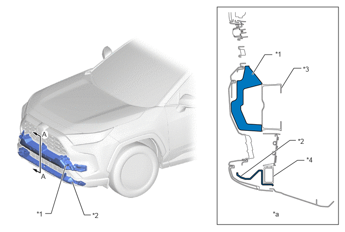
| *1 | Front Bumper Energy Absorber No. 2 | *2 | Front Bumper Absorber Lower |
| *3 | Front Bumper Reinforcement | *4 | Front Bumper Reinforcement No. 2 |
| *a | A - A Cross Section | - | - |
Reduction of Pedestrian Head Injury
A deformation stroke is ensured for the front part of the engine hood to absorb impact during collisions, creating a structure that reduces the impact to the head of a pedestrian during collisions.
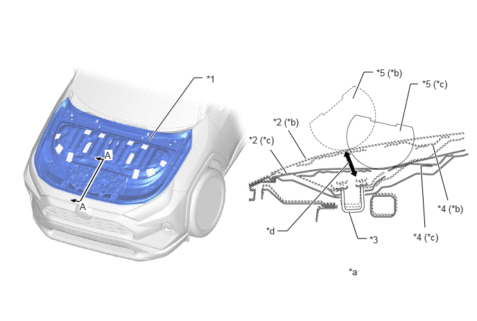
| *1 | Hood Sub-assembly | *2 | Hood Panel |
| *3 | Hood Lock Hook | *4 | Hood Panel Reinforcement |
| *5 | Headform Impactor | - | - |
| *a | A - A Cross Section | *b | Before Collision |
| *c | After Collision | *d | Stroke |
A collision absorption structure is used for the front fender extension and apron fender side extension, creating a structure that reduces the impact to the head of a pedestrian during collisions where the pedestrian contacts the fender.
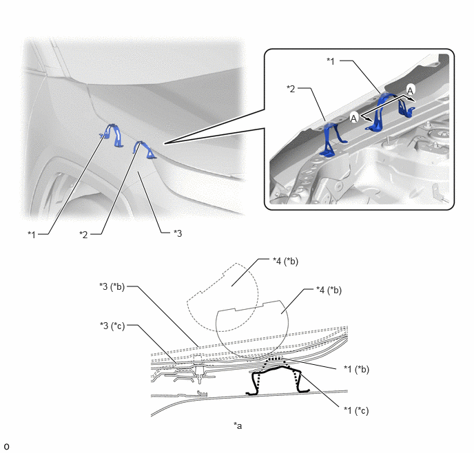
| *1 | Front Fender Extension Top RH | *2 | Apron Fender Side Extension RH |
| *3 | Front Fender Panel RH | *4 | Headform Impactor |
| *a | A - A Cross Section | *b | Before Collision |
| *c | After Collision | - | - |
A collision absorption structure is used for the cowl top ventilator louver sub-assembly.
During a collision with a pedestrian, the cowl top ventilator louver sub-assembly (*1 in illustration) collapse similar to a pantograph in order to absorb impact load. (*a in illustration)
When the pedestrian contacts the vehicle, the wiper pivot detaches to ensure the stroke space in consideration of reducing the extent of the pedestrian's injuries. (*b in illustration)
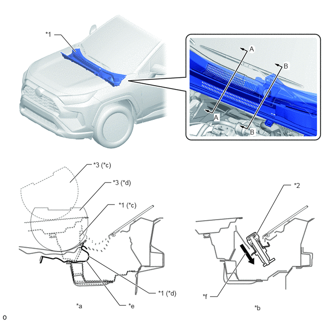
| *1 | Cowl Top Ventilator Louver Sub-assembly | *2 | Wiper Pivot |
| *3 | Headform Impactor | - | - |
| *a | A - A Cross Section | *b | B - B Cross Section |
| *c | Before Collision | *d | After Collision |
| *e | Pantograph Structure | *f | Stroke |