INTERIOR PANELS / TRIM FRONT CONSOLE BOX DISASSEMBLY
CAUTION / NOTICE / HINT
- HINT:
- ·
Use the same procedure as for the LHD and RHD vehicles.
·The procedure listed below is for the LHD vehicles.
PROCEDURE

 58920A
1.REMOVE REAR CONSOLE ARMREST ASSEMBLY
Open the rear console armrest assembly.
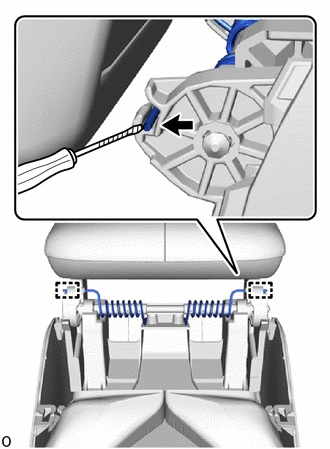

|
Protective Tape |
Using a thin-bladed screwdriver, detach the guide and remove the console box mounting bracket spring both side.
- HINT:
-
Tape the thin-bladed screwdriver tip before use.
Close the rear console armrest assembly.
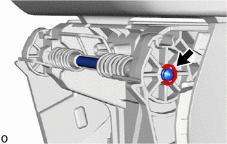
Remove the E-ring.
- HINT:
- ·
When installing, reinstallation is not required.
·The E-ring may be installed on the opposite side.
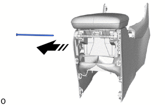

|
Remove in this Direction |
Pull in the direction of the arrow shown in the illustration to remove the console compartment door stopper pin.
- HINT:
-
When the E-ring is installed on the opposite side, remove the pin in the opposite direction.
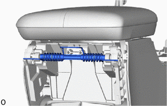
Remove the console box mounting bracket spring with console box spacer.
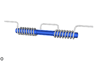
Pull a console box spacer out of the console box mounting bracket spring.
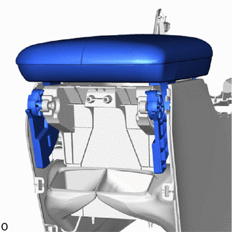
Remove the rear console armrest assembly.
58987A
2.REMOVE NO. 2 CONSOLE BOX RETAINER (for Manual Transaxle)
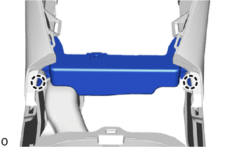
Detach the claw and remove the No. 2 console box retainer.
58912D
3.REMOVE NO. 2 BOX PANEL (for LHD)
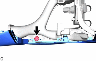
Detach the clip.
except Manual Transaxle:
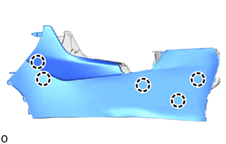
Detach the claw.
for Manual Transaxle:
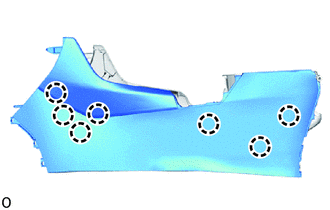
Detach the claw.
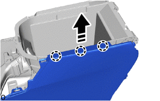
|
|
Remove in this Direction |
Lift up in the direction indicated by the arrow shown in the illustration to detach the claw and remove the No. 2 box panel.
58912D
4.REMOVE NO. 2 BOX PANEL (for RHD)
except Manual Transaxle:
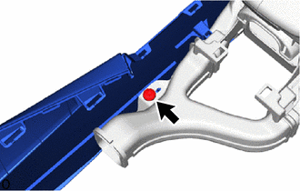
Detach the clip.
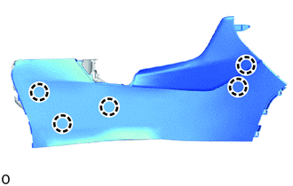
Detach the claw.
for Manual Transaxle:
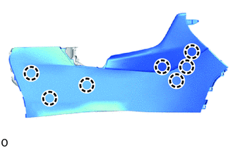
Detach the claw.
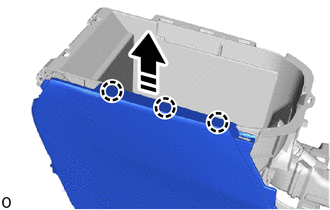
|
|
Remove in this Direction |
Lift up in the direction indicated by the arrow shown in the illustration to detach the claw and remove the No. 2 box panel.
58985
5.REMOVE CONSOLE BOX RETAINER (except Manual Transaxle)
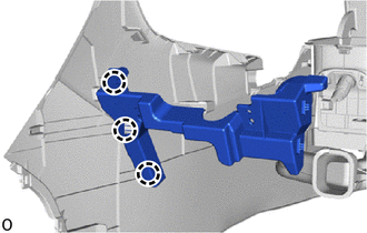
Detach the claw and remove the console box retainer.
58985
6.REMOVE CONSOLE BOX RETAINER (for Manual Transaxle)
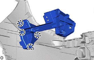
Detach the claw and remove the console box retainer.
58911B
7.REMOVE NO. 1 BOX PANEL (for LHD)
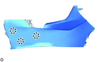
Detach the claw.
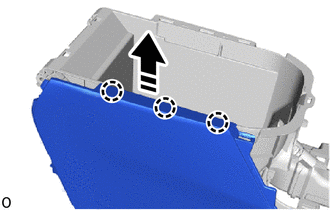
|
|
Remove in this Direction |
Lift up in the direction indicated by the arrow shown in the illustration to detach the claw and remove the No. 1 box panel.
58911B
8.REMOVE NO. 1 BOX PANEL (for RHD)
for Manual Transaxle:
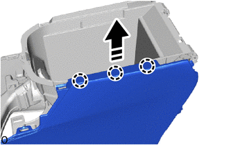
Detach the clip.
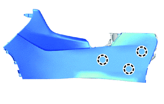
Detach the claw.
|
|
Remove in this Direction |
Lift up in the direction indicated by the arrow shown in the illustration to detach the claw and remove the No. 1 box panel.
35978
9.REMOVE SHIFT POSITION INDICATOR (except Manual Transaxle)
for Automatic Transaxle:
for CVT:
K120: Click hereDrivetrain>K120 (MULTIDRIVE / CVT)>SHIFT LEVER>DISASSEMBLY
K120F: Click hereDrivetrain>K120F (MULTIDRIVE / CVT)>SHIFT LEVER>DISASSEMBLY
for HV Model:
84390A
10.REMOVE BRAKE WARNING SWITCH ASSEMBLY (for Manual Transaxle)
84010D
11.REMOVE INTEGRATION CONTROL AND PANEL ASSEMBLY
58808
12.REMOVE SHIFTING HOLE COVER SUB-ASSEMBLY
except Manual Transaxle:
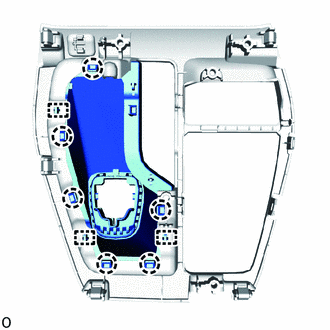
Detach the claw and guide and remove the shifting hole cover sub-assembly.
for Manual Transaxle:
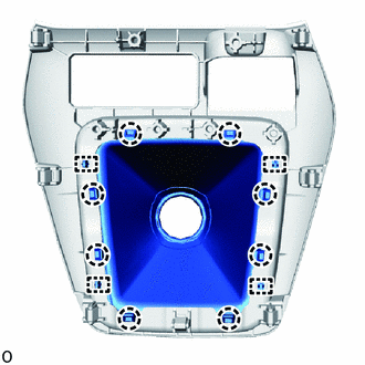
Detach the claw and guide and remove the shifting hole cover sub-assembly.
86190C
13.REMOVE NO. 1 STEREO JACK ADAPTER ASSEMBLY (w/ Radio Receiver)
55524A
14.REMOVE SWITCH BASE HOLE COVER (w/o Radio Receiver)
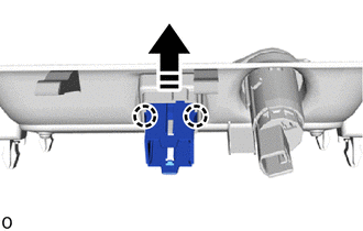
except Manual Transaxle:
|
|
Remove in this Direction |
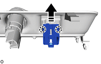
Detach the claw and remove the switch base hole cover in the direction indicated by the arrow shown in the illustration.
for Manual Transaxle:
|
|
Remove in this Direction |
Detach the claw and remove the switch base hole cover in the direction indicated by the arrow shown in the illustration.
85530
15.REMOVE NO. 1 POWER OUTLET SOCKET ASSEMBLY
85535B
16.REMOVE NO. 1 POWER OUTLET SOCKET COVER