RM3620E
_58
Vehicle Interior
_076051
METER / GAUGE / DISPLAY
_0370499
LIGHT CONTROL RHEOSTAT
G
METER / GAUGE / DISPLAY LIGHT CONTROL RHEOSTAT INSPECTION
PROCEDURE

 84119
1.INSPECT LIGHT CONTROL RHEOSTAT
a.
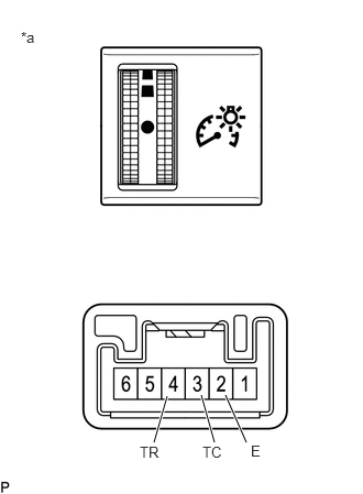
2.333,4.188 2.135,3.74
true
2.031,4.188 1.906,3.74
true
1.458,4.188 1.583,3.75
true
0.198,0.271 0.51,0.427
0.313,0.156
10
false
*a
2.375,4.188 2.563,4.396
0.188,0.208
10
false
E
1.917,4.198 2.188,4.427
0.271,0.229
10
false
TC
1.323,4.198 1.594,4.427
0.271,0.229
10
false
TR
| *a | Component without harness connected
(Light Control Rheostat) |
Measure the resistance according to the value(s) in the table below.
- Standard Resistance:
Tester Connection Condition Specified Condition 4 (TR) - 2 (E) Light control rheostat knob fully downwards (MIN) Below 50 Ω Light control rheostat knob between MIN. and MAX The value changes gradually (Between 0 to 12 kΩ) Light control rheostat knob fully upwards (MAX) 8 to 12 kΩ 3 (TC) - 2 (E) Light control rheostat knob not fully upwards Below 50 Ω Light control rheostat knob fully upwards (Tail cancel switch is on) 8 to 12 kΩ
If the result is not as specified, replace the light control rheostat.
b.
Check the illumination.
i.
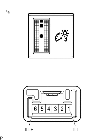
2.542,4.219 2.375,3.729
true
0.979,4.208 1.115,3.74
true
0.198,0.313 0.51,0.469
0.313,0.156
10
false
*a
2.469,4.25 3.083,4.448
0.615,0.198
10
false
ILL-
0.844,4.24 1.458,4.438
0.615,0.198
10
false
ILL+
| *a | Component without harness connected
(Light Control Rheostat) |
Apply auxiliary battery voltage to the light control rheostat and check that it illuminates.
- OK:
Measurement Condition Specified Condition Auxiliary battery positive (+) → 6 (ILL+)
Auxiliary battery negative (-) → 1 (ILL-)Illuminates
If the result is not as specified, replace the light control rheostat.