HYBRID / BATTERY CONTROL WATER PUMP WITH MOTOR REMOVAL
PROCEDURE

 1.DRAIN COOLANT (for Inverter)
G9040
2.REMOVE INVERTER WATER PUMP ASSEMBLY
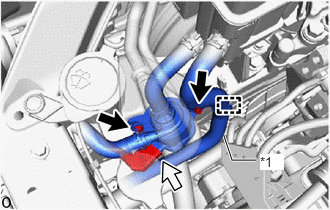
| *1 | No. 5 Inverter Cooling Hose |
Disconnect the inverter water pump assembly connector.
- NOTICE:
- To prevent coolant from entering the inverter water pump assembly connector, perform the following procedure.
-
Apply insulating tape to the connectors of the wire harness and inverter water pump assembly.
Disengage the No. 5 inverter cooling hose clamp.
Remove the 2 bolts to remove the inverter water pump assembly from the HV water pump bracket sub-assembly.
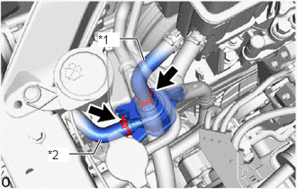
| *1 | No. 2 Inverter Cooling Hose |
| *2 | No. 3 Inverter Cooling Hose |
Slide the 2 clips and disconnect the No. 2 inverter cooling hose and No. 3 inverter cooling hose to remove the inverter water pump assembly.
- NOTICE:
- ·
Put pieces of cloth into the pipes and disconnected hoses or cover the pipes and hoses with plastic bags to prevent foreign matter from entering the inverter water pump assembly and inverter cooling system.
·Do not apply excessive force to the hoses.
·If the inverter water pump assembly has been struck or dropped, replace it.
G9031A
3.REMOVE HV WATER PUMP BRACKET SUB-ASSEMBLY
- HINT:
-
This procedure is only performed when the HV water pump bracket sub-assembly is being replaced with a new one.
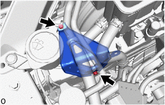
Remove the 2 bolts and HV water pump bracket sub-assembly from the front side member sub-assembly.