MIRROR (EXT) OUTER REAR VIEW MIRROR REMOVAL
CAUTION / NOTICE / HINT
w/ Panoramic view monitor system:
The necessary procedures (adjustment, calibration, initialization or registration) that must be performed after parts are installed, removed or replaced during the outer rear view mirror assembly and side television camera assembly removal/installation are shown below.
| Replacement Part or Procedure | Necessary Procedures | Effects/Inoperative Functions when not Performed | Link |
|---|---|---|---|
·
Side television camera assembly LH ·
Outer rear view mirror assembly LH ·
Side television camera assembly RH ·
Outer rear view mirror assembly RH |
Side television camera view adjustment | Panoramic view monitor system (for Gasoline model) | ( ) |
| Replacement Part or Procedure | Necessary Procedures | Effects/Inoperative Functions when not Performed | Link |
|---|---|---|---|
·
Side television camera assembly LH ·
Outer rear view mirror assembly LH ·
Side television camera assembly RH ·
Outer rear view mirror assembly RH |
Side television camera view adjustment | Panoramic view monitor system (for HV model) | ()
|
- HINT:
- ·
Use the same procedure for the RH and LH sides.
·The procedure listed below is for the LH side.
PROCEDURE

 69278B
1.REMOVE FRONT DOOR INSIDE HANDLE BEZEL LH
74642A
2.REMOVE FRONT DOOR ASSIST GRIP COVER LH
3.REMOVE MULTIPLEX NETWORK MASTER SWITCH ASSEMBLY WITH FRONT DOOR ARMREST BASE PANEL (for Driver Side)
4.REMOVE POWER WINDOW REGULATOR SWITCH ASSEMBLY WITH FRONT DOOR ARMREST BASE PANEL (for Front Passenger Side)
67602
5.REMOVE FRONT DOOR TRIM BOARD SUB-ASSEMBLY LH
6.REMOVE OUTER MIRROR INSTALL HOLE COVER LH
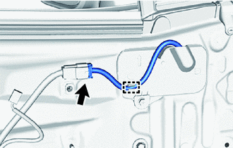
Disconnect the connector.
Detach the clamp.
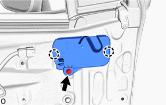
Remove the screw.
Detach the claw to remove the outer mirror install hole cover LH.
87940
7.REMOVE OUTER REAR VIEW MIRROR ASSEMBLY LH
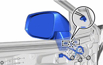

|
Protective Tape |
Remove the 3 nuts.
- NOTICE:
-
Hold the outer rear view mirror assembly LH with one hand so that it does not drop.
Using a thin-bladed screwdriver, detach the claw and guide to remove the outer rear view mirror assembly LH.
- HINT:
-
Tape the thin-bladed screwdriver tip before use.