RM3620E
_51
Engine / Hybrid System
_076502
A25A-FKS EMISSION CONTROL
_0372402
PURGE VALVE(w/o Canister Pump Module)
A
A25A-FKS EMISSION CONTROL PURGE VALVE(w/o Canister Pump Module) INSTALLATION
PROCEDURE

 25860
1.INSTALL PURGE VALVE (PURGE VSV)
a.
0.833,1.281 1.406,1.281
true
2.083,1.854 2.083,1.469
true
0.865,0.813 1.438,0.813
true
2.01,1.854 2.198,2.052
0.188,0.198
10
true
*1
0.646,1.198 0.823,1.385
0.177,0.188
10
true
*2
1.063,2.552 1.25,2.719
0.188,0.167
10
false
*a
0.281,3.479 0.479,3.677
0.198,0.198
10
false
*b
0.667,2.802 0.865,2.99
0.198,0.188
10
false
*c
1.948,3.938 2.146,4.135
0.198,0.198
10
false
*d
0.646,0.719 0.854,0.927
0.208,0.208
10
true
*3
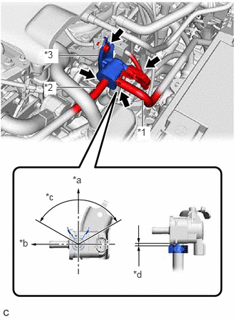
| *1 | No. 1 Fuel Vapor Feed Hose |
| *2 | No. 2 Fuel Vapor Feed Hose |
| *3 | Purge Valve (Purge VSV) |
| *a | Up |
| *b | Front |
| *c | 120° (Clip tab area) |
| *d | 2 to 7 mm (0.0787 to 0.276 in.) |
Install the purge valve (purge VSV) to the purge VSV bracket with the bolt.
- Torque:
- 10 N*m (102 kgf*cm, 7 ft.*lbf)
b.
Connect the No. 2 fuel vapor feed hose to the purge valve (purge VSV).
c.
Connect the No. 1 fuel vapor feed hose to the purge valve (purge VSV) and slide the clip to secure it.
- HINT:
-
Engage the clip within the area shown in the illustration.
d.
Connect the purge valve (purge VSV) connector.