RM3620E
_51
Engine / Hybrid System
_076384
M20A-FKS ENGINE CONTROL
_0372636
MASS AIR FLOW METER
G
M20A-FKS ENGINE CONTROL MASS AIR FLOW METER INSPECTION
PROCEDURE

 22204
1.INSPECT MASS AIR FLOW METER SUB-ASSEMBLY
a.
0.927,1 1.74,1
true
0.74,0.906 1.052,1.063
0.313,0.156
10
false
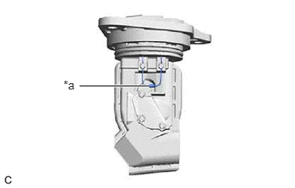
*a
| *a | Thermistor |
Perform a visual check for any foreign matter on the temperature sensor (thermistor) of the mass air flow meter sub-assembly shown in the illustration.
- OK:
There is no foreign matter.
If the result is not as specified, replace the mass air flow meter sub-assembly.
b.
1.219,1.167 0.885,0.583
0.885,0.583 0.615,0.583
true
1.906,1.156 2.25,0.573
2.25,0.573 2.51,0.573
true
0.073,0.052 0.417,0.354
0.344,0.302
10
false
*a
0.302,0.5 0.646,0.677
0.344,0.177
10
false
THA
2.552,0.49 2.896,0.667
0.344,0.177
10
false
E2G
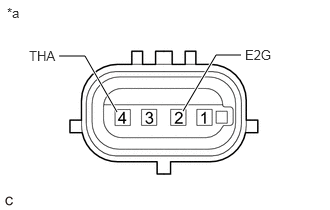
| *a | Component without harness connected
(Mass Air Flow Meter Sub-assembly) |
Measure the resistance according to the value(s) in the table below.
- Standard Resistance:
Tester Connection Condition Specified Condition 4 (THA) - 2 (E2G) -20°C (-4°F) 13.6 to 18.4 kΩ 20°C (68°F) 2.21 to 2.69 kΩ 60°C (140°F) 0.49 to 0.67 kΩ
If the result is not as specified, replace the mass air flow meter sub-assembly.