EG62F MANUAL TRANSMISSION / TRANSAXLE INPUT SHAFT INSPECTION
PROCEDURE

 1.INSPECT 6TH GEAR SUB-ASSEMBLY THRUST CLEARANCE
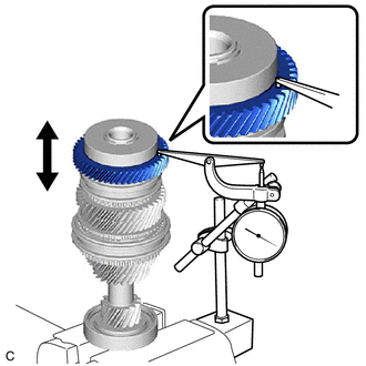
Using a dial indicator, measure the 6th gear sub-assembly thrust clearance.
- Standard Clearance:
0.180 to 0.650 mm (0.00709 to 0.0256 in.)
- Maximum Clearance:
0.650 mm (0.0256 in.)
If the clearance exceeds the maximum, replace the 6th gear sub-assembly, No. 3 transmission clutch hub or input shaft.
2.INSPECT 5TH GEAR THRUST CLEARANCE
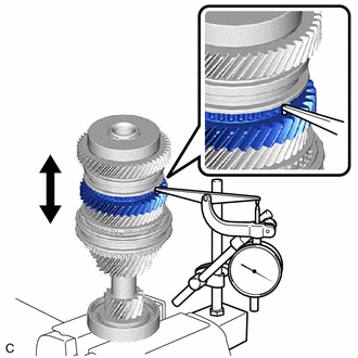
Using a dial indicator, measure the 5th gear thrust clearance.
- Standard Clearance:
0.170 to 0.700 mm (0.00669 to 0.0276 in.)
- Maximum Clearance:
0.700 mm (0.0276 in.)
If the clearance exceeds the maximum, replace the 5th gear, No. 3 transmission clutch hub or input shaft.
3.INSPECT 4TH GEAR THRUST CLEARANCE
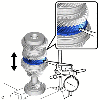
Using a dial indicator, measure the 4th gear thrust clearance.
- Standard Clearance:
0.150 to 0.780 mm (0.00591 to 0.0307 in.)
- Maximum Clearance:
0.780 mm (0.0307 in.)
If the clearance exceeds the maximum, replace the 4th gear, No. 2 transmission clutch hub or input shaft.
4.INSPECT 3RD GEAR THRUST CLEARANCE
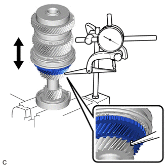
Using a dial indicator, measure the 3rd gear thrust clearance.
- Standard Clearance:
0.210 to 0.480 mm (0.00827 to 0.0189 in.)
- Maximum Clearance:
0.480 mm (0.0189 in.)
If the clearance exceeds the maximum, replace the 3rd gear, No. 2 transmission clutch hub or input shaft.
5.INSPECT 6TH GEAR SUB-ASSEMBLY RADIAL CLEARANCE
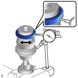
Using a dial indicator, measure the 6th gear sub-assembly radial clearance between the 6th gear sub-assembly and input shaft.
- Standard Clearance:
0.012 to 0.038 mm (0.000472 to 0.00150 in.)
- Maximum Clearance:
0.038 mm (0.00150 in.)
If the clearance exceeds the maximum, replace the 6th gear sub-assembly or input shaft.
6.INSPECT 5TH GEAR RADIAL CLEARANCE
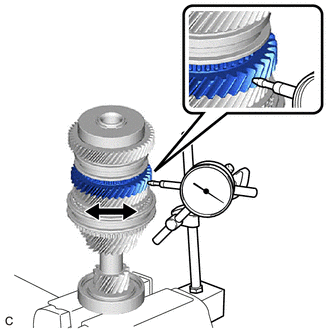
Using a dial indicator, measure the 5th gear radial clearance between the 5th gear and input shaft.
- Standard Clearance:
0.012 to 0.038 mm (0.000472 to 0.00150 in.)
- Maximum Clearance:
0.038 mm (0.00150 in.)
If the clearance exceeds the maximum, replace the 5th gear or input shaft.
7.INSPECT 4TH GEAR RADIAL CLEARANCE
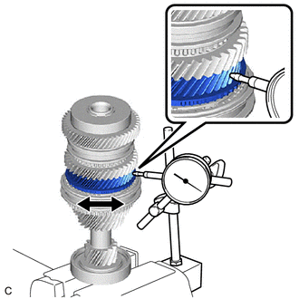
Using a dial indicator, measure the 4th gear radial clearance between the 4th gear and input shaft.
- Standard Clearance:
0.012 to 0.038 mm (0.000472 to 0.00150 in.)
- Maximum Clearance:
0.038 mm (0.00150 in.)
If the clearance exceeds the maximum, replace the 4th gear or input shaft.
8.INSPECT 3RD GEAR RADIAL CLEARANCE
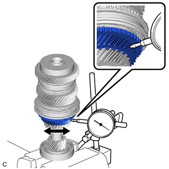
Using a dial indicator, measure the 3rd gear radial clearance between the 3rd gear and input shaft.
- Standard Clearance:
0.009 to 0.047 mm (0.000354 to 0.00185 in.)
- Maximum Clearance:
0.047 mm (0.00185 in.)
If the clearance exceeds the maximum, replace the 3rd gear, 3rd gear needle roller bearing or input shaft.
33311
9.INSPECT INPUT SHAFT
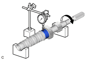
Using a dial indicator and 2 V-blocks, check the input shaft runout.
- Maximum Runout:
0.03 mm (0.00118 in.)
If the runout exceeds the maximum, replace the input shaft.
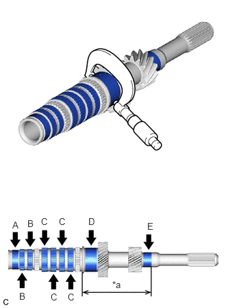
| *a | 118.6 mm (4.67 in.) |
Using a micrometer, measure the outer diameter of the input shaft journal surface at the locations indicated.
- Standard Outer Diameter:
- Part (A):
32.984 to 33.000 mm (1.29858 to 1.29921 in.)
- Part (B):
36.393 to 36.403 mm (1.43279 to 1.43319 in.)
- Part (C):
40.993 to 41.003 mm (1.61389 to 1.61429 in.)
- Part (D):
41.290 to 41.300 mm (1.62559 to 1.62598 in.)
- Part (E):
25.002 to 25.018 mm (0.98433 to 0.98496 in.)
- Minimum Outer Diameter:
- Part (A):
32.984 mm (1.29858 in.)
- Part (B):
36.393 mm (1.43279 in.)
- Part (C):
40.993 mm (1.61389 in.)
- Part (D):
41.290 mm (1.62559 in.)
- Part (E):
25.002 mm (0.98433 in.)
If any of the outer diameters are less than the minimum, replace the input shaft.
33337
10.INSPECT 6TH GEAR SUB-ASSEMBLY
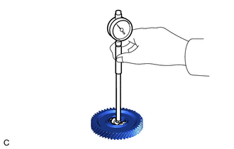
Using a cylinder gauge, measure the inside diameter of the 6th gear sub-assembly.
- Standard Inside Diameter:
36.415 to 36.431 mm (1.43366 to 1.43429 in.)
- Maximum Inside Diameter:
36.431 mm (1.43429 in.)
If the inside diameter exceeds the maximum, replace the 6th gear sub-assembly.
33336
11.INSPECT 5TH GEAR
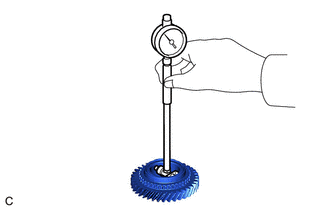
Using a cylinder gauge, measure the inside diameter of the 5th gear.
- Standard Inside Diameter:
41.015 to 41.031 mm (1.61476 to 1.61539 in.)
- Maximum Inside Diameter:
41.031 mm (1.61539 in.)
If the inside diameter exceeds the maximum, replace the 5th gear.
33334
12.INSPECT 4TH GEAR
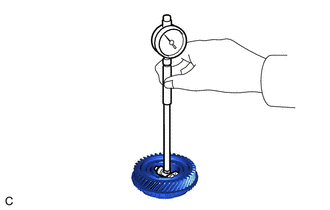
Using a cylinder gauge, measure the inside diameter of the 4th gear.
- Standard Inside Diameter:
41.015 to 41.031 mm (1.61476 to 1.61539 in.)
- Maximum Inside Diameter:
41.031 mm (1.61539 in.)
If the inside diameter exceeds the maximum, replace the 4th gear.
33333
13.INSPECT 3RD GEAR
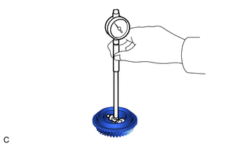
Using a cylinder gauge, measure the inside diameter of the 3rd gear.
- Standard Inside Diameter:
47.309 to 47.325 mm (1.86256 to 1.86319 in.)
- Maximum Inside Diameter:
47.325 mm (1.86319 in.)
If the inside diameter exceeds the maximum, replace the 3rd gear.
33396C
14.INSPECT NO. 5 SYNCHRONIZER RING(MTM) (for 6th Gear Sub-assembly)
Check for wear and damage.
Coat the 6th gear sub-assembly cone with gear oil.
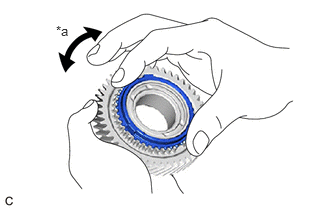
| *a | Lock |
Turn the No. 5 synchronizer ring(MTM) (for 6th gear sub-assembly) in one direction while pushing it against the 6th gear sub-assembly cone.
Check that the No. 5 synchronizer ring(MTM) (for 6th gear sub-assembly) locks.
If the No. 5 synchronizer ring(MTM) (for 6th gear sub-assembly) does not lock, replace the No. 5 synchronizer ring(MTM) (for 6th gear sub-assembly).
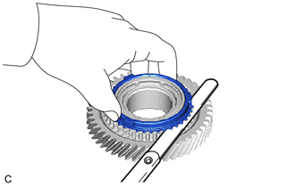
Using a feeler gauge, measure the clearance between the No. 5 synchronizer ring(MTM) (for 6th gear sub-assembly) and 6th gear sub-assembly spline end.
- Standard Clearance:
0.730 to 1.530 mm (0.0287 to 0.0602 in.)
- Minimum Clearance:
0.730 mm (0.0287 in.)
If the clearance is less than the minimum, replace the No. 5 synchronizer ring(MTM) (for 6th gear sub-assembly).
33396C
15.INSPECT NO. 5 SYNCHRONIZER RING(MTM) (for 5th Gear)
Check for wear and damage.
Coat the 5th gear cone with gear oil.
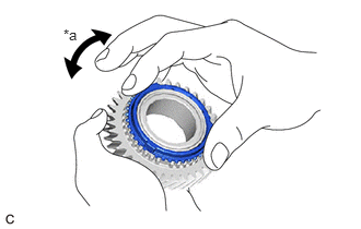
| *a | Lock |
Turn the No. 5 synchronizer ring(MTM) (for 5th gear) in one direction while pushing it against the 5th gear cone.
Check that the No. 5 synchronizer ring(MTM) (for 5th gear) locks.
If the No. 5 synchronizer ring(MTM) (for 5th gear) does not lock, replace the No. 5 synchronizer ring(MTM) (for 5th gear).
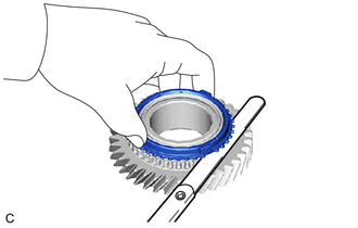
Using a feeler gauge, measure the clearance between the No. 5 synchronizer ring(MTM) (for 5th gear) and 5th gear spline end.
- Standard Clearance:
0.730 to 1.530 mm (0.0287 to 0.0602 in.)
- Minimum Clearance:
0.730 mm (0.0287 in.)
If the clearance is less than the minimum, replace the No. 5 synchronizer ring(MTM) (for 5th gear).
33369B
16.INSPECT NO. 4 SYNCHRONIZER RING
Check for wear and damage.
Coat the 4th gear cone with gear oil.
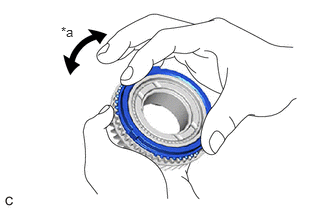
| *a | Lock |
Turn the No. 4 synchronizer ring in one direction while pushing it against the 4th gear cone.
Check that the No. 4 synchronizer ring locks.
If the No. 4 synchronizer ring does not lock, replace the No. 4 synchronizer ring.
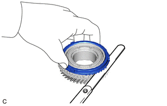
Using a feeler gauge, measure the clearance between the No. 4 synchronizer ring and 4th gear spline end.
- Standard Clearance:
0.880 to 1.720 mm (0.0346 to 0.0677 in.)
- Minimum Clearance:
0.880 mm (0.0346 in.)
If the clearance is less than the minimum, replace the No. 4 synchronizer ring.
33369
17.INSPECT NO. 3 SYNCHRONIZER RING
Check for wear and damage.
Coat the 3rd gear cone with gear oil.
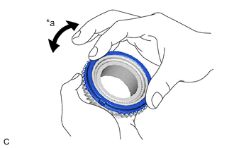
| *a | Lock |
Turn the No. 3 synchronizer ring in one direction while pushing it against the 3rd gear cone.
Check that the No. 3 synchronizer ring locks.
If the No. 3 synchronizer ring does not lock, replace the No. 3 synchronizer ring.
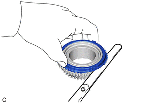
Using a feeler gauge, measure the clearance between the No. 3 synchronizer ring and 3rd gear spline end.
- Standard Clearance:
0.780 to 1.620 mm (0.0307 to 0.0638 in.)
- Minimum Clearance:
0.780 mm (0.0307 in.)
If the clearance is less than the minimum, replace the No. 3 synchronizer ring.
33395
18.INSPECT NO. 3 TRANSMISSION HUB SLEEVE
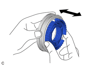
Check the sliding condition between the No. 3 transmission hub sleeve and No. 3 transmission clutch hub.
Check that the edges of the No. 3 transmission hub sleeve splines are not worn down.
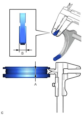
Using a vernier caliper, measure the width of the No. 3 transmission hub sleeve groove (A) and thickness of the claw part on the No. 3 gear shift fork assembly (B), and calculate the clearance.
- Standard Clearance:
(A) - (B) = 0.09 to 0.51 mm (0.00354 to 0.0201 in.)
If the clearance is out of specification, replace the No. 3 transmission hub sleeve and No. 3 gear shift fork assembly.
33364
19.INSPECT NO. 2 TRANSMISSION HUB SLEEVE
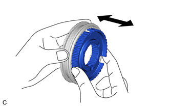
Check the sliding condition between the No. 2 transmission hub sleeve and No. 2 transmission clutch hub.
Check that the edges of the No. 2 transmission hub sleeve splines are not worn down.
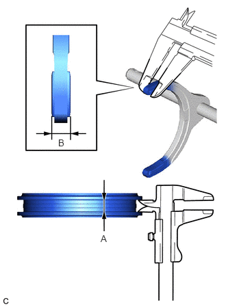
Using a vernier caliper, measure the width of the No. 2 transmission hub sleeve groove (A) and thickness of the claw part on the No. 2 gear shift fork assembly (B), and calculate the clearance.
- Standard Clearance:
(A) - (B) = 0.09 to 0.51 mm (0.00354 to 0.0201 in.)
If the clearance is out of specification, replace the No. 2 transmission hub sleeve and No. 2 gear shift fork assembly.