PARKING BRAKE ELECTRIC PARKING BRAKE SYSTEM(w/ Vacuum Brake Booster) P085013 Neutral Switch Circuit Open P18301C Neutral Switch Supply Voltage Circuit Voltage Out of Range
DESCRIPTION
This DTC is stored when an abnormal neutral position switch signal is detected by the skid control ECU (brake actuator assembly).
| DTC No. | Detection Item | DTC Detection Condition | Trouble Area | Memory | Note |
|---|---|---|---|---|---|
| P085013 | Neutral Switch Circuit Open | ·
Diagnosis Condition: - ·
Malfunction Status: (One of the following conditions is met): Abnormal neutral position switch power supply voltage and +BS terminal voltage Open or short in neutral position switch circuit ·
Detection Time: 0.1 seconds or more |
·
Neutral position switch ·
Wire harness or connector ·
Stop and start system ·
ECM |
DTC stored | An electric parking brake system malfunction is displayed on the multi-information display. |
| P18301C | Neutral Switch Supply Voltage Circuit Voltage Out of Range | ·
Diagnosis Condition: - ·
Malfunction Status: (One of the following conditions is met): Abnormal neutral position switch power supply voltage and +BS terminal voltage Open or short in neutral position switch circuit ·
Detection Time: 0.1 seconds or more |
·
Neutral position switch ·
Wire harness or connector ·
Stop and start system ·
ECM |
DTC stored | An electric parking brake system malfunction is displayed on the multi-information display. |
| Vehicle Condition | ||||
|---|---|---|---|---|
| Pattern 1 | Pattern 2 | Pattern 3 | ||
| Diagnosis Condition | - | - | - | - |
| Malfunction Status | Neutral position switch open circuit is detected | ○ | - | - |
| Neutral position switch short circuit is detected | - | ○ | - | |
| Neutral position switch power supply voltage and +BS terminal voltage are judged to be abnormal | - | - | ○ | |
| Detection Time | 0.1 seconds or more | 0.1 seconds or more | 0.1 seconds or more | |
| Number of Trips | 1 trip | 1 trip | 1 trip | |
| Vehicle Condition | ||||
|---|---|---|---|---|
| Pattern 1 | Pattern 2 | Pattern 3 | ||
| Diagnosis Condition | - | - | - | - |
| Malfunction Status | Neutral position switch open circuit is detected | ○ | - | - |
| Neutral position switch short circuit is detected | - | ○ | - | |
| Neutral position switch power supply voltage and +BS terminal voltage are judged to be abnormal | - | - | ○ | |
| Detection Time | 0.1 seconds or more | 0.1 seconds or more | 0.1 seconds or more | |
| Number of Trips | 1 trip | 1 trip | 1 trip | |
WIRING DIAGRAM
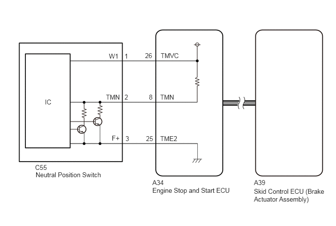
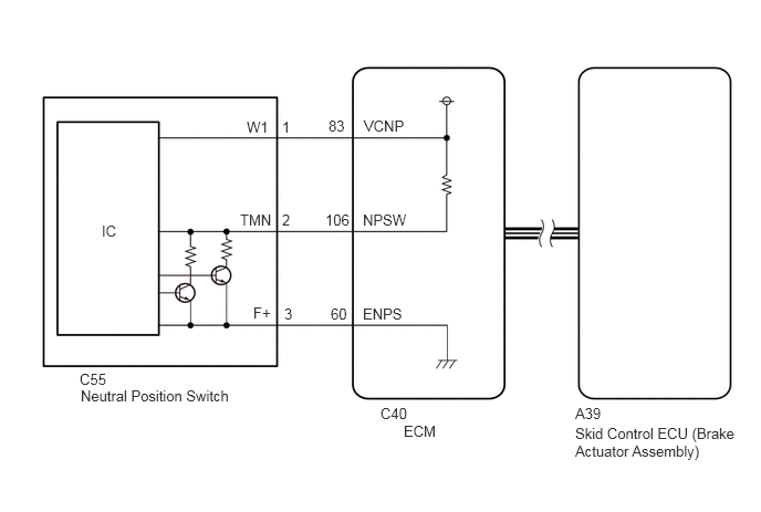
CAUTION / NOTICE / HINT
- NOTICE:
-
The electric parking brake may still operate up to 20 seconds after the ignition switch is turned off. Before disconnecting connectors or fuses, turn the ignition switch off and wait 20 seconds or more.
PROCEDURE
Check the vehicle specification.
- Result:
Result Proceed to w/ Stop and Start System A w/o Stop and Start System B
A
B
Check for DTCs in the stop and start system.
Click hereEngine / Hybrid System>STOP AND START>STOP AND START SYSTEM(for M20A-FKS)>DTC CHECK / CLEAR
- Powertrain > Stop and Start > Trouble Codes
- 50001 392
- Result:
Proceed to NEXT
NEXT
Connect the GTS to the DLC3.
Turn the ignition switch to ON.
Turn the GTS on.
Enter the following menus: Powertrain / Engine / Data List / Neutral Position Switch.
- Powertrain > Engine > Data List
-
Tester Display Neutral Position Switch - 50003 372 881
Read the value when the shift lever is in neutral and any other position.
- OK:
Tester Display Condition Normal Condition Neutral Switch Shift lever in neutral ON Shift lever in any position other than neutral OFF
- Result:
Proceed to OK NG
OK
Click hereGeneral>INTRODUCTION>HOW TO TROUBLESHOOT ECU CONTROLLED SYSTEMS>HOW TO PROCEED WITH TROUBLESHOOTING
NG
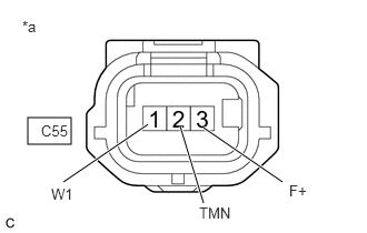
| *a | Front view of wire harness connector
(to Neutral Position Switch) |
- HINT:
-
Make sure that the connector is properly connected. If it is not, securely connect it and check for DTCs again.
Disconnect the C55 neutral position switch connector.
Turn the ignition switch to ON.
Measure the voltage according to the value(s) in the table below.
- Standard Voltage:
Tester Connection Condition Specified Condition C55-1 (W1) - Body ground Ignition switch ON 4.5 to 5.5 V C55-2 (TMN) - Body ground Ignition switch ON 3.0 to 5.0 V
Turn the ignition switch off and wait for at least 30 seconds.
Measure the resistance according to the value(s) in the table below.
- Standard Resistance:
Tester Connection Condition Specified Condition C55-1 (W1) - C55-2 (TMN) Ignition switch off 0.95 to 1.05 kΩ C55-3 (F+) - Body ground Always Below 1 Ω
- Result:
Proceed to OK NG
OK
NG
Disconnect the C40 ECM connector.
Disconnect the neutral position switch connector.
Measure the resistance according to the value(s) in the table below.
- Standard Resistance:
Tester Connection Condition Specified Condition C40-83 (VCNP) - C55-1 (W1) Always Below 1 Ω C40-60 (ENPS) - C55-3 (F+) Always Below 1 Ω C40-106 (NPSW) - C55-2 (TMN) Always Below 1 Ω C40-83 (VCNP) or C55-1 (W1) - Body ground Always 10 kΩ or higher C40-60 (ENPS) or C55-3 (F+) - Body ground Always 10 kΩ or higher C40-106 (NPSW) or C55-2 (TMN) - Body ground Always 10 kΩ or higher
- Result:
Proceed to OK NG
OK
NG