K120 MULTIDRIVE / CVT CONTINUOUSLY VARIABLE TRANSAXLE SYSTEM DIAGNOSIS SYSTEM
EURO-OBD (EUROPEAN SPEC)

When troubleshooting Europe On-Board Diagnostic (Euro-OBD) vehicles, an OBD scan tool (complying with ISO 15765-4) must be connected to the vehicle. Various data output from the vehicle's TCM can then be read.
Euro-OBD regulations require that the vehicle's on-board computer illuminate the Malfunction Indicator Lamp (MIL) on the instrument panel when the computer detects a malfunction in any of the following:
The emission control system/components
The powertrain control components which affect vehicle emission
The computer
In addition, the applicable Diagnostic Trouble Codes (DTCs) prescribed by ISO 15765-4 are stored in the TCM memory. If the malfunction does not recur in 3 consecutive trips, the MIL turns off automatically but the DTCs remain stored in the TCM memory.
To check for DTCs, connect the GTS or OBD scan tool to the Data Link Connector 3 (DLC3) of the vehicle.
The scan tool displays DTCs, the freeze frame data and a variety of engine data.
The DTCs and freeze frame data can be cleared using the scan tool.
Click hereDrivetrain>K120 (MULTIDRIVE / CVT)>CONTINUOUSLY VARIABLE TRANSAXLE SYSTEM>DTC CHECK / CLEAR
M-OBD
When troubleshooting a Multiplex On-Board Diagnostic (M-OBD) vehicles, the GTS must be connected to the vehicle. Various data output from the ECM can then be read.
OBD regulations require that the vehicle on-board computer illuminates the MIL on the instrument panel when the computer detects a malfunction in:
The emission control system/components
The powertrain control components which affect vehicle emission
The computer
In addition, the applicable Diagnostic Trouble Codes (DTCs) prescribed by ISO 15765-4 are stored in the ECM memory. If the malfunction does not reoccur in 3 consecutive trips, the MIL turns off automatically but the DTCs remain stored in the ECM memory.
NORMAL MODE AND CHECK MODE (GTS Only)
The diagnosis system operates in normal mode during normal vehicle use. In normal mode, 2-trip detection logic is used to ensure accurate detection of malfunctions. Check mode is also available to technicians as an option. In check mode, 1-trip detection logic is used when reproducing malfunction symptoms for increasing the ability of the system to detect malfunctions, including intermittent malfunctions.
2-TRIP DETECTION LOGIC
When a malfunction is first detected, the malfunction is temporarily stored in the TCM memory (1st trip). If the same malfunction is detected during the subsequent driving cycle, the MIL is illuminated (2nd trip).
FREEZE FRAME DATA
The TCM records vehicle and driving condition information as freeze frame data the moment a DTC is stored. When troubleshooting, freeze frame data can be helpful in determining whether the vehicle was moving or stationary, whether the engine was warmed up or not and whether the air-fuel ratio was lean or rich, as well as other data recorded at the time of a malfunction.
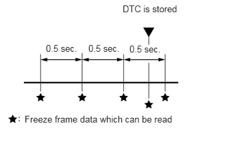
The GTS displays freeze frame data recorded at five different points: 1) 3 times before the DTC is stored, 2) once when the DTC is stored, and 3) once after the DTC is stored. The data can be used to reproduce the vehicle condition around the time of the malfunction. The data may be helpful in determining the cause of a malfunction. It may also be helpful in determining whether a DTC is being caused by a temporary malfunction.
LIST OF FREEZE FRAME DATA
- Powertrain > Transmission
-
Tester Display Total Distance Traveled Total Distance Traveled - Unit Vehicle Speed Engine Speed Calculate Load Coolant Temperature Intake Air Temperature Ambient Temperature Engine Run Time Battery Voltage Glow Indicator Supported Throttle Position Sensor No.1 Voltage % Starter SW Stop Light SW TC Terminal MIL ON Run Distance Running Time from MIL ON Time after DTC Cleared Distance from DTC Cleared Warmup Cycle Cleared DTC Accel Position from EFI NSS Sensor Speed NSS Sensor Voltage NO Sensor Speed NO Sensor Voltage NT Sensor Speed NC1 Sensor Speed NC1 Sensor Voltage Belt Clamping Force Sensor Shift SW Status (P Range) Shift SW Status (R Range) Shift SW Status (N Range) Shift SW Status (N,P Range) Shift SW Status (N,P Range) Supported Sport Shift Up SW Sport Shift Down SW Shift SW Status (S Range) Shift SW Status (D Range) A/T Oil Temperature No.1 ATF Thermal Degradation Estimate CVT Oil Press Calibration NT Sensor Voltage Acceleration Sensor Voltage Synchronize Stroke Sensor Position Synchronize Stroke Sensor Voltage Status of Synchronize Lock Up Status CVT Shift Status Ratio Shift Mode Solenoid (SLU) Solenoid (SLS) High/Low Solenoid (SLS) MAX/MIN Solenoid (SLP) Solenoid (SLG) Solenoid (SL1) Solenoid (SL2) Acceleration Sensor Calibration Acceleration Sensor Learn Value
DATA LINK CONNECTOR 3 (DLC3)
Check the DLC3.
Click hereGeneral>INTRODUCTION>HOW TO TROUBLESHOOT ECU CONTROLLED SYSTEMS>GENERAL INFORMATION
BATTERY VOLTAGE
- Standard voltage:
11 to 14 V
If the voltage is below 11 V, recharge or replace the battery.
MIL (Malfunction Indicator Lamp)
The MIL is illuminated when the ignition switch is turned to ON (with the engine not running).
If the MIL does not illuminate, check the MIL circuit.
Click hereEngine / Hybrid System>M20A-FKS (ENGINE CONTROL)>SFI SYSTEM>MIL Circuit
The MIL will turn off when the engine is started. If the MIL remains illuminated, the diagnosis system has detected a malfunction or abnormality in the system.