HYBRID / BATTERY CONTROL REAR MOTOR GENERATOR CONTROL SYSTEM(for NICKEL METAL HYDRIDE BATTERY) TERMINALS OF ECU
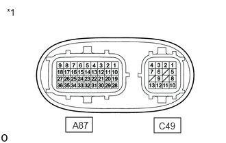
| *1 | Inverter with Converter Assembly |
- HINT:
-
Since the inverter with converter assembly uses waterproof connectors, the voltage and waveforms cannot be inspected directly. Standard voltage readings and waveforms are indicated for reference only.
| Terminal No.
(Symbol) |
Wiring Color | Input/Output | Terminal Description | Condition | Standard Condition |
|---|---|---|---|---|---|
| A87-1 (RRFG) - A87-28 (RRF) | G - BR | Output | Rear motor resolver signal | Rear motor resolver running | Pulse generation
(Waveform 7) |
| A87-3 (HMCH) - A87-9 (GND1) | B - W-B | Input/Output | Communication signal | Power switch on (IG) | Pulse generation
(Waveform 4) |
| A87-4 (HMCL) - A87-9 (GND1) | W - W-B | Input/Output | Communication signal | Power switch on (IG) | Pulse generation
(Waveform 4) |
| A87-6 (HSDN) - A87-9 (GND1) | G - W-B | Input | MG shutdown signal | Power switch on (READY) | 0 to 1 V |
| A87-10 (RSNG) - A87-19 (RSN) | R - L | Input | Rear motor resolver signal | Rear motor resolver running | Pulse generation
(Waveform 7) |
| A87-16 (GI) - A87-9 (GND1) | R - W-B | Input | Camshaft position sensor signal | Power switch on (READY), engine running | Pulse generation
(Waveform 2) |
| A87-17 (NE) - A87-9 (GND1) | B - W-B | Input | Crankshaft position sensor signal | Power switch on (READY), engine running | Pulse generation
(Waveform 3) |
| A87-18 (ABFS) - A87-9 (GND1) | LG - W-B | Input | Airbag activation signal | Power switch on (READY) | Pulse generation
(Waveform 9) |
| A87-20 (RCSG) - A87-29 (RCS) | Y - W | Input | Rear motor resolver signal | Rear motor resolver running | Pulse generation
(Waveform 7) |
| A87-22 (CANH) - A87-9 (GND1) | V - W-B | Input/Output | CAN communication signal | Power switch on (IG) | Pulse generation
(Waveform 1) |
| A87-24 (CNH2) - A87-9 (GND1) | LG - W-B | Input/Output | CAN communication signal | Power switch on (IG) | Pulse generation
(Waveform 8) |
| A87-26 (IGCT) - A87-9 (GND1) | BE - W-B | Input | Motor generator control ECU (MG ECU) power source | Power switch on (IG) | 11 to 14 V |
| A87-27 (+B3) - A87-9 (GND1) | L - W-B | Input | Discharge control power source | Always | 11 to 14 V |
| A87-31 (CANL) - A87-9 (GND1) | W - W-B | Input/Output | CAN communication signal | Power switch on (IG) | Pulse generation
(Waveform 1) |
| A87-33 (CNL2) - A87-9 (GND1) | W - W-B | Input/Output | CAN communication signal | Power switch on (IG) | Pulse generation
(Waveform 8) |
| A87-35 (+B2) - A87-9 (GND1) | GR - W-B | Input | Motor generator control ECU (MG ECU) power source | Power switch on (IG) | 11 to 14 V |
| A87-36 (+B) - A87-9 (GND1) | W - W-B | Input | Motor generator control ECU (MG ECU) power source | Power switch on (IG) | 11 to 14 V |
| C49-1 (MSN) - C49-2 (MSNG) | G - Y | Input | Motor resolver signal | Motor resolver running | Pulse generation
(Waveform 5) |
| C49-3 (MCSG) - C49-4 (MCS) | B - L | Input | Motor resolver signal | Motor resolver running | Pulse generation
(Waveform 5) |
| C49-5 (MRF) - C49-6 (MRFG) | W - R | Output | Motor resolver reference signal | Motor resolver running | Pulse generation
(Waveform 5) |
| C49-8 (GRF) - C49-9 (GRFG) | SB - V | Output | Generator resolver reference signal | Generator resolver running | Pulse generation
(Waveform 6) |
| C49-10 (GSN) - C49-11 (GSNG) | GR - P | Input | Generator resolver signal | Generator resolver running | Pulse generation
(Waveform 6) |
| C49-12 (GCSG) - C49-13 (GCS) | BR - LG | Input | Generator resolver signal | Generator resolver running | Pulse generation
(Waveform 6) |
- NOTICE:
-
Do not measure the voltage or waveform on the sealed side of the inverter with converter assembly connector. Doing so may damage the connector because the connector is waterproof.
Oscilloscope waveforms
- HINT:
-
Oscilloscope waveforms shown in the illustrations are examples for reference only. Noise, chattering, etc. are not shown.
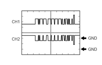
Waveform 1 (CAN communication signal)
| Item | Content |
|---|---|
| Terminal | CH1: A87-22 (CANH) - A87-9 (GND1)
CH2: A87-31 (CANL) - A87-9 (GND1) |
| Equipment Setting | 1 V/DIV., 50 μs./DIV. |
| Condition | Power switch on (IG) |
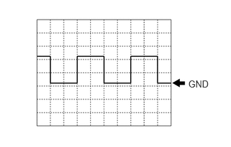
Waveform 2 (camshaft position sensor signal)
| Item | Content |
|---|---|
| Terminal | A87-16 (GI) - A87-9 (GND1) |
| Equipment Setting | 5 V/DIV., 20 ms./DIV. |
| Condition | Power switch on (READY), engine running |
- HINT:
-
The wavelength becomes shorter as the engine speed increases.
Waveform 3 (crankshaft position sensor signal)
| Item | Content |
|---|---|
| Terminal | A87-17 (NE) - A87-9 (GND1) |
| Equipment Setting | 5 V/DIV., 20 ms./DIV. |
| Condition | Power switch on (READY), engine running |
- HINT:
-
The wavelength becomes shorter as the engine speed increases.
Waveform 4 (communication signal)
| Item | Content |
|---|---|
| Terminal | CH1: A87-3 (HMCH) - A87-9 (GND1)
CH2: A87-4 (HMCL) - A87-9 (GND1) |
| Equipment Setting | 1 V/DIV., 50 μs./DIV. |
| Condition | Power switch on (IG) |
- HINT:
-
The waveform will vary depending on the content of the digital communication (digital signal).
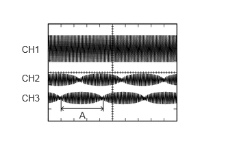
Waveform 5 (motor resolver signal)
| Item | Content |
|---|---|
| Terminal | CH1: C49-5 (MRF) - C49-6 (MRFG)
CH2: C49-1 (MSN) - C49-2 (MSNG) CH3: C49-4 (MCS) - C49-3 (MCSG) |
| Equipment Setting | CH1: 10 V/DIV., 1 ms./DIV.
CH2: 5 V/DIV., 1 ms./DIV. CH3: 5 V/DIV., 1 ms./DIV. |
| Condition | Motor resolver running |
- HINT:
-
The width indicated by (A) becomes shorter as the rotor speed increases.
Waveform 6 (generator resolver signal)
| Item | Content |
|---|---|
| Terminal | CH1: C49-8 (GRF) - C49-9 (GRFG)
CH2: C49-10 (GSN) - C49-11 (GSNG) CH3: C49-13 (GCS) - C49-12 (GCSG) |
| Equipment Setting | CH1: 10 V/DIV., 1 ms./DIV.
CH2: 5 V/DIV., 1 ms./DIV. CH3: 5 V/DIV., 1 ms./DIV. |
| Condition | Generator resolver running |
- HINT:
-
The width indicated by (A) becomes shorter as the rotor speed increases.
Waveform 7 (rear motor resolver signal)
| Item | Content |
|---|---|
| Terminal | CH1: A87-28 (RRF) - A87-1 (RRFG)
CH2: A87-19 (RSN) - A87-10 (RSNG) CH3: A87-29 (RCS) - A87-20 (RCSG) |
| Equipment Setting | CH1: 10 V/DIV., 1 ms./DIV.
CH2: 5 V/DIV., 1 ms./DIV. CH3: 5 V/DIV., 1 ms./DIV. |
| Condition | Rear motor resolver running |
- HINT:
-
The width indicated by (A) becomes shorter as the rotor speed increases.
Waveform 8 (communication signal)
| Item | Content |
|---|---|
| Terminal | CH1: A87-24 (CNH2) - A87-9 (GND1)
CH2: A87-33 (CNL2) - A87-9 (GND1) |
| Equipment Setting | 1 V/DIV., 50 μs./DIV. |
| Condition | Power switch on (IG) |
- HINT:
-
The waveform will vary depending on the content of the digital communication (digital signal).
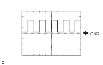
Waveform 9 (Airbag activation signal)
| Item | Content |
|---|---|
| Terminal | A87-18 (ABFS) - A87-9 (GND1) |
| Equipment Setting | 5 V/DIV., 150 ms./DIV. |
| Condition | Power switch on (READY) |