Home › Engine / Hybrid System › A25A-FXS (ENGINE CONTROL) › SFI SYSTEM (w/ Canister Pump Module) › from 2019.02
RM3620E _51 Engine / Hybrid System _076383 A25A-FXS ENGINE CONTROL _0372716 SFI SYSTEM(w/ Canister Pump Module) C

A25A-FXS ENGINE CONTROL  SFI SYSTEM(w/ Canister Pump Module)  P24187F  Evaporative Emission System Switching Valve Control Circuit Actuator Stuck Off  


DTC SUMMARY

DTC No. Detection Item DTC Detection Condition Trouble Area MIL Memory Note
P24187F Evaporative Emission System Switching Valve Control Circuit Actuator Stuck Off Following condition is met during key-off EVAP monitor:
·

EVAP pressure change when vent valve closed (on) less than 0.3 kPa [0.04 psi]


·

Canister pump module (reference orifice, leak detection pump, vent valve)

·

Connector/wire harness (Canister pump module - ECM)

·

Canister (filter inside canister clogged)

·

ECM


Comes on DTC stored SAE Code: P2420

DTC No. Monitoring Item Detection Timing Detection Logic SAE Code
P24187F Vent valve stuck open (vent) EVAP monitoring
(power switch off)
2 trip P2420

HINT:

The vent valve is built into the canister pump module.


DESCRIPTION

MONITOR DESCRIPTION

P24187F: Vent valve stuck open (vent)

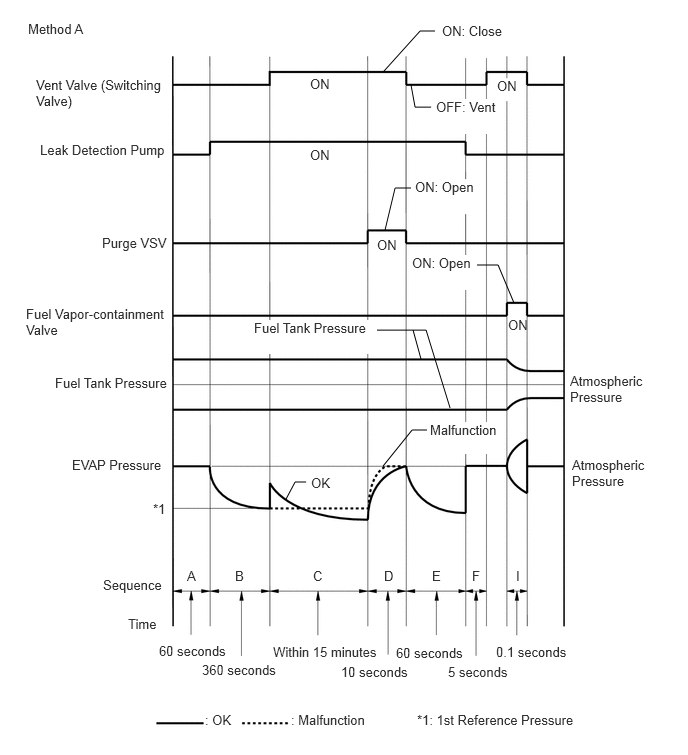
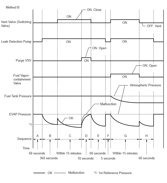
In operation C, the vent valve turns on (closed) and the EVAP system pressure is then measured by the ECM using the canister pressure sensor to conduct an EVAP leak check. If the pressure does not increase when the vent valve is open, the ECM interprets this as the vent valve being stuck open. In this case the ECM will illuminate the MIL and store this DTC.
A319541E01
4.385,3.74 4.302,3.438 false 2.979,5.198 3.073,5.021 3.073,5.021 3.188,5.021 false 3.99,4.854 4.292,4.479 4.292,4.479 4.448,4.479 false 3.927,3.438 4.438,3.438 4.438,3.438 4.688,4.25 false 4.969,2.76 5.188,2.76 5.188,2.76 5.354,3.156 false 4.281,1.958 4.115,1.958 4.115,1.958 4.01,2.396 false 4.49,1.115 4.323,1.115 4.323,1.115 4.281,0.885 false 4.531,0.323 4.375,0.323 4.375,0.323 3.99,0.75 false 0.292,0.219 1.521,0.417 1.229,0.198 10 false Method A 0.375,0.802 1.729,1.271 1.354,0.469 10 false Vent Valve (Switching Valve) 0.417,1.479 1.75,1.927 1.333,0.448 10 false Leak Detection Pump 1.063,2.448 1.76,2.813 0.698,0.365 10 false Purge VSV 0.271,3.188 1.74,3.594 1.469,0.406 10 false Fuel Vapor-containment Valve 0.573,3.906 1.865,4.563 1.292,0.656 10 false Fuel Tank Pressure 0.75,4.76 1.76,5.146 1.01,0.385 10 false EVAP Pressure 1.594,5.219 1.865,5.563 0.271,0.344 10 false *1 1.073,6.01 1.729,6.417 0.656,0.406 10 false Sequence 1.333,6.417 1.729,6.667 0.396,0.25 10 false Time 1.656,6.698 2.615,6.958 0.958,0.26 10 false 60 seconds 2.104,6.896 3.063,7.156 0.958,0.26 10 false 360 seconds 2.844,6.708 4.365,6.969 1.521,0.26 10 false Within 15 minutes 3.552,6.917 4.365,7.167 0.813,0.25 10 false 10 seconds 4.125,6.719 4.938,6.969 0.813,0.25 10 false 60 seconds 5.167,6.708 5.979,6.958 0.813,0.25 10 false 0.1 seconds 5.958,4.76 6.792,5.146 0.833,0.385 10 false Atmospheric Pressure 5.938,3.885 6.771,4.271 0.833,0.385 10 false Atmospheric Pressure 5.292,3.302 6.125,3.688 0.833,0.385 10 false ON 3.24,4.948 3.625,5.198 0.385,0.25 10 false OK 4.479,4.396 5.208,4.729 0.729,0.333 10 true Malfunction 2.646,3.333 3.896,3.688 1.25,0.354 10 true Fuel Tank Pressure 4.323,1.865 4.99,2.229 0.667,0.365 10 true ON: Open 4.542,1.031 5.208,1.396 0.667,0.365 10 true OFF: Vent 3.927,2.469 4.146,2.813 0.219,0.344 10 false ON 4.604,0.24 5.271,0.604 0.667,0.365 10 true ON: Close 3.229,1.531 3.448,1.875 0.219,0.344 10 false ON 3.229,0.792 3.448,1.135 0.219,0.344 10 false ON 5.177,0.813 5.396,1.052 0.219,0.24 10 true ON 4.292,2.656 4.958,3.021 0.667,0.365 10 true ON: Open 1.948,5.917 2.333,6.167 0.385,0.25 10 false A 2.448,5.917 2.833,6.167 0.385,0.25 10 false B 3.26,5.917 3.646,6.167 0.385,0.25 10 false C 4,5.917 4.385,6.167 0.385,0.25 10 false D 4.5,5.917 4.885,6.167 0.385,0.25 10 false E 4.917,5.917 5.302,6.167 0.385,0.25 10 false F 5.375,5.917 5.76,6.167 0.385,0.25 10 false I 2.135,7.417 2.948,7.667 0.813,0.25 10 false : OK 3.031,7.417 3.844,7.667 0.813,0.25 10 false : Malfunction 4.344,7.417 6.771,7.677 2.427,0.26 10 false *1: 1st Reference Pressure 4.667,6.917 5.479,7.167 0.813,0.25 10 false 5 seconds

A319542E01
5.073,4.906 5.354,3.677 false 3.271,0.833 3.563,0.417 3.563,0.417 3.677,0.417 false 6.083,0.979 6.135,1.115 6.135,1.115 6.25,1.115 false 3.667,2.458 3.802,2.052 3.802,2.052 3.917,2.052 false 5.667,3.177 5.854,2.813 5.854,2.813 6.083,2.813 false 4.896,4.125 5.115,3.667 5.115,3.667 5.5,3.667 false 3.698,4.896 4.052,4.469 4.052,4.469 4.26,4.469 false 2.656,5.271 2.792,5.073 2.792,5.073 2.906,5.073 false 0.25,0.229 1.479,0.427 1.229,0.198 10 false Method B 0.042,0.854 1.438,1.25 1.396,0.396 10 false Vent Valve (Switching Valve) 0.052,1.698 1.448,2.094 1.396,0.396 10 false Leak Detection Pump 0.677,2.51 1.5,2.771 0.823,0.26 10 false Purge VSV 0.573,3.156 1.344,3.792 0.771,0.635 10 false Fuel Vapor-containment Valve 0.188,4.042 1.583,4.594 1.396,0.552 10 false Fuel Tank Pressure 0.396,4.823 1.792,5.375 1.396,0.552 10 false EVAP Pressure 1.24,5.271 1.563,5.479 0.323,0.208 10 false *1 0.74,5.875 1.833,6.125 1.094,0.25 10 false Sequence 0.969,6.281 2.063,6.531 1.094,0.25 10 false Time 1.24,6.5 2.333,6.75 1.094,0.25 10 false 60 seconds 1.708,6.708 2.802,6.958 1.094,0.25 10 false 360 seconds 2.417,6.5 3.927,6.75 1.51,0.25 10 false Within 15 minutes 3.323,6.719 4.833,6.969 1.51,0.25 10 false 10 seconds 3.844,6.5 5.354,6.75 1.51,0.25 10 false 60 seconds 4.333,6.719 5.844,6.969 1.51,0.25 10 false 5 seconds 1.969,7.344 3.479,7.594 1.51,0.25 10 false : OK 5.948,6.708 7.083,7 1.135,0.292 10 false 60 seconds 4.833,6.5 6.344,6.75 1.51,0.25 10 false Within 15 minutes 2.854,7.333 3.813,7.563 0.958,0.229 10 false : Malfunction 4.021,7.344 6.177,7.583 2.156,0.24 10 false *1: 1st Reference Pressure 3.729,0.333 4.406,0.729 0.677,0.396 10 true ON: Close 6.302,1.031 6.979,1.427 0.677,0.396 10 true OFF: Vent 3.958,1.979 4.635,2.375 0.677,0.396 10 true ON: Open 6.115,2.729 6.792,3.125 0.677,0.396 10 true ON: Open 5.573,3.573 6.938,3.917 1.365,0.344 10 true Atmospheric Pressure 4.302,4.385 5.042,4.781 0.74,0.396 10 true Malfunction 2.854,0.625 3.146,0.875 0.292,0.25 10 false ON 5.25,0.885 5.542,1.135 0.292,0.25 10 false ON 2.833,1.708 3.125,1.958 0.292,0.25 10 false ON 5.24,1.698 5.531,1.948 0.292,0.25 10 false ON 5.24,3.208 5.531,3.458 0.292,0.25 10 false ON 2.948,4.99 3.24,5.24 0.292,0.25 10 false OK 1.563,5.75 1.854,6 0.292,0.25 10 false A 2.104,5.75 2.396,6 0.292,0.25 10 false B 2.958,5.75 3.25,6 0.292,0.25 10 false C 3.656,5.75 3.948,6 0.292,0.25 10 false D 4.177,5.75 4.469,6 0.292,0.25 10 false E 4.604,5.75 4.896,6 0.292,0.25 10 false F 5.333,5.75 5.625,6 0.292,0.25 10 false G 6.24,5.75 6.531,6 0.292,0.25 10 false H 3.604,2.521 3.896,2.771 0.292,0.25 10 false ON

MONITOR STRATEGY

Required Sensors/Components Canister pump module
Purge VSV
Frequency of Operation Once per driving cycle

CONFIRMATION DRIVING PATTERN

NOTICE:
·

The Evaporative System Check (Automatic Mode) consists of 9 steps performed automatically by the GTS. It takes a maximum of approximately 40 minutes.

·

Do not perform the Evaporative System Check when the fuel tank is more than 90% full because the cut-off valve may be closed, making the fuel tank leak check unavailable.

·

Do not start the engine during this operation.

·

When the temperature of the fuel is 35°C (95°F) or higher, a large amount of vapor will from and any check result will be inaccurate. When performing the Evaporative System Check, keep the fuel temperature less than 35°C (95°F).


1.

Connect the GTS to the DLC3.

2.

Turn the power switch on (IG).

3.

Turn the GTS on.

4.

Clear the DTCs (even if no DTCs are stored, perform the clear DTC procedure).

5.

Turn the power switch off and wait for at least 30 seconds.

6.

Turn the power switch on (IG).

7.

Turn the GTS on.

8.

Enter the following menus: Powertrain / Engine / Utility / Evaporative System Check / Automatic Mode.

9.

After the Evaporative System Check is completed, check for All Readiness by entering the following menus: Powertrain / Engine / Utility / All Readiness.

10.

Input the DTC: P24187F.

11.

Check the DTC judgment result.

GTS Display Description
NORMAL
·

DTC judgment completed

·

System normal


ABNORMAL
·

DTC judgment completed

·

System abnormal


INCOMPLETE
·

DTC judgment not completed

·

Perform driving pattern after confirming DTC enabling conditions


HINT:
·

If the judgment result is NORMAL, the system is normal.

·

If the judgment result is ABNORMAL, the system is malfunctioning.


CAUTION / NOTICE / HINT

NOTICE:
·

Vehicle Control History may be stored in the hybrid vehicle control ECU assembly if the engine is malfunctioning. Certain vehicle condition information is recorded when Vehicle Control History is stored. Reading the vehicle conditions recorded in both the freeze frame data and Vehicle Control History can be useful for troubleshooting.

for 2WD: Click hereEngine / Hybrid System>HYBRID / BATTERY CONTROL>HYBRID CONTROL SYSTEM (for 2WD with NICKEL METAL HYDRIDE BATTERY)>VEHICLE CONTROL HISTORY

for 4WD/AWD: Click hereEngine / Hybrid System>HYBRID / BATTERY CONTROL>HYBRID CONTROL SYSTEM (for 4WD/AWD with NICKEL METAL HYDRIDE BATTERY)>VEHICLE CONTROL HISTORY

(Select Powertrain in Health Check and then check the time stamp data.)

Click hereEngine / Hybrid System>A25A-FXS (ENGINE CONTROL)>SFI SYSTEM (w/ Canister Pump Module)>DTC CHECK / CLEAR

·

If any "Engine Malfunction" Vehicle Control History item has been stored in the hybrid vehicle control ECU assembly, make sure to clear it. However, as all Vehicle Control History items are cleared simultaneously, if any Vehicle Control History items other than "Engine Malfunction" are stored, make sure to perform any troubleshooting for them before clearing Vehicle Control History.

for 2WD: Click hereEngine / Hybrid System>HYBRID / BATTERY CONTROL>HYBRID CONTROL SYSTEM (for 2WD with NICKEL METAL HYDRIDE BATTERY)>VEHICLE CONTROL HISTORY

for 4WD/AWD: Click hereEngine / Hybrid System>HYBRID / BATTERY CONTROL>HYBRID CONTROL SYSTEM (for 4WD/AWD with NICKEL METAL HYDRIDE BATTERY)>VEHICLE CONTROL HISTORY


PROCEDURE

1.GO TO EVAP SYSTEM

NEXT

END