RM3620E
_56
Audio / Visual / Telematics
_076049
TELEMATICS
_0389152
TELEMATICS SYSTEM(for ERA-GLONASS)
U
TELEMATICS TELEMATICS SYSTEM(for ERA-GLONASS) TERMINALS OF ECU
- HINT:
-
Check from the rear of the connector while it is connected to the components.
TELEPHONE TRANSCEIVER ASSEMBLY
4.594,0.25 5.01,0.5
0.417,0.25
1.24,0.229 1.656,0.479
0.417,0.25
2.49,0.24 2.906,0.49
0.417,0.25
4.708,0.302 5.323,0.5
0.615,0.198
10
false
H6
0.969,0.583 1.281,0.74
0.313,0.156
10
false
*a
2.229,0.583 2.542,0.74
0.313,0.156
10
false
*b
1.396,0.271 2.01,0.469
0.615,0.198
10
false
G
2.667,0.292 3.281,0.49
0.615,0.198
10
false
F
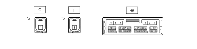
| *a | Connector Color: Gray (to GNSS Antenna) | *b | Connector Color: Blue (to Telephone Antenna) |
| Terminal No. (Symbol) | Wiring Color | Terminal Description | Condition | Specified Condition |
|---|---|---|---|---|
|
*: w/ Navigation System or w/ Audio and Visual System (for Radio and Display Type) |
||||
| H6-1 (+B) - H6-4 (E) | B - W-B | Power source (+B) | Always | 11 to 14 V |
| H6-4 (E) - Body ground | W-B - Body ground | Ground | Always | Below 1 Ω |
| H6-5 (SPO+) - H6-4 (E) | LA-BE - W-B | Sound signal | Audio system playing, or emergency call mode | A waveform synchronized with sound signals is output |
| H6-6 (SPO-) - H6-4 (E) | LA-L - W-B | Sound signal | Audio system playing, or emergency call mode | A waveform synchronized with sound signals is output |
| H6-7 (IG2) - H6-4 (E) | LG - W-B | Power source (IG) | Ignition switch ON | 11 to 14 V |
| Ignition switch off | Below 1 V | |||
| H6-8 (ACC) - H6-4 (E) | GR - W-B | Power source (ACC) | Ignition switch ACC | 11 to 14 V |
| Ignition switch off | Below 1 V | |||
| H6-9 (SLED) - H6-4 (E) | SB - W-B | Manual (SOS) switch illumination power supply | Ignition switch ACC | 11 to 14 V |
| Ignition switch off | Below 1 V | |||
| H6-10 (SPDP) - H6-4 (E) | GR - W-B | Vehicle speed signal | See "Check speedometer operation" in Operation Check
(  ) |
- |
| H6-11 (IND1) - H6-4 (E) | BR - W-B | Manual (SOS) switch indicator (red) illumination signal | For 10 seconds after ignition switch is turned to ON | 1 to 8.5 V |
| Ignition switch off | Below 1 V | |||
| H6-12 (IND2) - H6-4 (E) | LG - W-B | Manual (SOS) switch indicator (green) illumination signal | For 2 seconds after ignition switch is turned to ON and the manual (SOS) switch indicator (red) has illuminated for 10 seconds | 1 to 8.5 V |
| Ignition switch off | Below 1 V | |||
| H6-15 (CANP) | R | CAN communication signal | - | - |
| H6-16 (CANN) | W | CAN communication signal | - | - |
| H6-17 (MUTE) - H6-4 (E)* | BE - W-B | Mute signal | Audio system playing | 3.5 to 5 V |
| Emergency call mode | Below 1 V | |||
| H6-18 (MCO+) - H6-4 (E)* | SB - W-B | Sent microphone voice signal | Voice being input to telephone microphone assembly | A waveform synchronized with microphone voice signal is input |
| H6-19 (MCO-) - H6-4 (E)* | V - W-B | Microphone voice signal | Always | Below 1 V |
| H6-23 (ILL+) - H6-4 (E) | W - W-B | Illumination signal | Light control switch off | Below 1 V |
| Light control switch in tail or head position | 11 to 14 V | |||
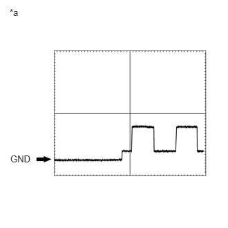
| H6-24 (GSW) - H6-4 (E) | BE - W-B | Collision detection signal | Ignition switch ON | Pulse generation
(Refer to waveform 1) |
| H6-26 (SIG-) - H6-4 (E) | BR - W-B | Ground | Always | Below 1 Ω |
| H6-27 (SIG1) - H6-4 (E) | GR - W-B | Manual (SOS) switch condition signal | Manual (SOS) switch not pressed | 2.0 to 2.3 V |
| Manual (SOS) switch pressed | Below 1 V | |||
| H6-32 (SGND) - H6-4 (E) | Shielded - W-B | Shield ground | Always | Below 1 Ω |
| H6-33 (MCVD) - H6-4 (E) | B - W-B | Microphone power supply | Ignition switch off | Below 1 V |
| Ignition switch ACC | 4 to 6 V | |||
| H6-34 (MCI+) - H6-4 (E) | W - W-B | Receive microphone voice signal | Voice being input to telephone microphone assembly | A waveform synchronized with microphone voice signal is input |
| H6-35 (MCI-) - H6-4 (E) | R - W-B | Receive microphone voice signal | Always | Below 1 V |
a.
0.156,2.313 0.552,2.542
0.396,0.229
10
false
GND
0.146,0.104 0.458,0.26
0.313,0.156
10
false
*a
| *a | Waveform 1 |
Oscilloscope waveform:
i.
Waveform 1
| Item | Condition |
|---|---|
| Tester connection | H6-24 (GSW) - H6-4 (E) |
| Tool setting | 5.0 V/DIV., 20 ms/DIV. |
| Vehicle condition | Ignition switch ON |
RADIO AND DISPLAY RECEIVER ASSEMBLY
w/o Navigation System: Click hereAudio / Visual / Telematics>AUDIO / VIDEO>AUDIO AND VISUAL SYSTEM (for Radio and Display Type)>TERMINALS OF ECU
w/ Navigation System: Click hereAudio / Visual / Telematics>NAVIGATION / MULTI INFO DISPLAY>NAVIGATION SYSTEM>TERMINALS OF ECU